Consider the Source Part 1: What is a Phase Locked Loop?
In this two-part blog we’ll look at how network analyzers generate signals. The phase locked loop is the bread and butter of analog signal generation, and understanding how phase locked loops work is key to understanding network analyzer block diagrams.
What Is A Phase Locked Loop And How Do They Work?
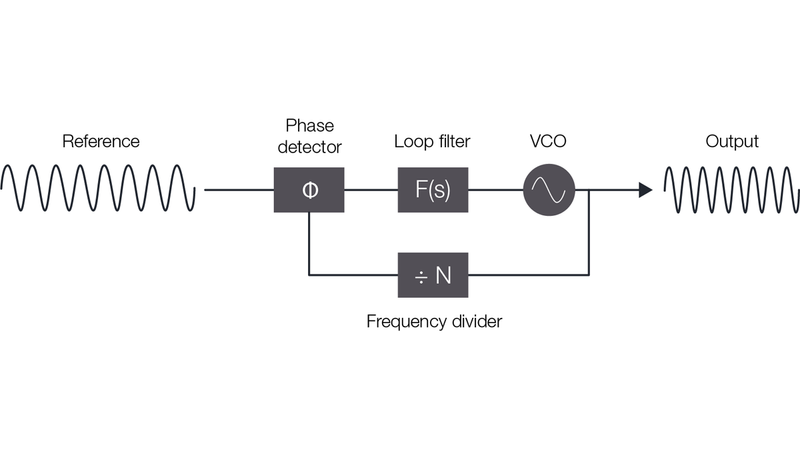
A PLL enables high-frequency signal generation based on a stable, low frequency reference. Figure 1 below shows a general PLL block diagram. A stable, low-frequency reference signal drives a voltage-controlled oscillator (VCO) to output a signal N times the reference frequency. On basic PLLs, N is an integer, but more advanced circuitry enables N to be a noninteger. This type of design is known as fractional-N synthesis.
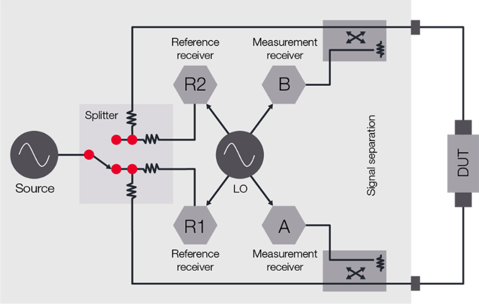
The ability of the PLL to reliably generate high-frequency signals makes it a great candidate for network analyzer signal sources. You can easily sweep across broad frequency ranges by adjusting N. The figure below shows a general network analyzer block diagram with a PLL-based source.
The source generates a test signal that the splitter routes to a reference receiver and the DUT. Measurement receivers sample the transmitted and reflected signals from the DUT. The network analyzer compares the measurements between the reference receivers and the measurement receivers, providing reflected and transmitted signal measurements as relative fractions of the incident test signal.
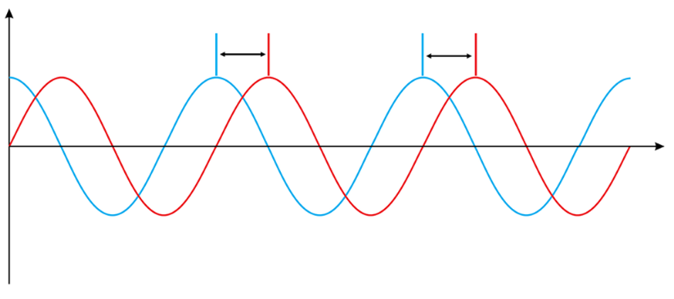
By sampling the test signal before and after it reaches the device under test (DUT), network analyzers can apply vector error correction for extremely accurate measurements – discontinuities are ratioed out of the measurement. This is important when we consider that the PLL source locks the stimulus and output together by an arbitrary phase difference, meaning your test signal will start at an arbitrary phase. But that’s okay for traditional network analyzer measurements like S-parameters, because the instrument measures the DUT’s response relative to the test signal, not relative to an absolute scale.
That’s enough relatives and absolutes to make your head spin, but the key takeaway is this: phase-locked loops make excellent signal sources for general-purpose network analysis.
However, modern designs containing amplifiers and frequency converters push the limits of what network analyzers can do. For example, when characterizing frequency converters with internal local oscillators, phase noise in the test system and the DUT can contribute to phase errors. If the results include phase errors, it’s impossible to know whether the phase noise came from the network analyzer or the DUT.

Modern mixers and frequency converters also push the limits of a network analyzer’s capabilities. Getting consistent measurements for operating bandwidths as wide as 3.2 GHz at 29 GHz often requires averaging multiple sweeps to reduce the noise.
So what do you do when you’re on the cutting edge of RF and you need to perform advanced network analyzer measurements as efficiently as possible? Find out next week in Part 2, or if you don’t want to wait download the white paper to read about how we upgraded the PNA and PNA-X to make sure they continue to be your go-to as devices continue to go up in frequency and down in size.
$300,000 in test gear prizes up for grabs.
Accurate test gear accelerates innovation – so don’t miss Keysight University Live from the Lab. Join us for an exclusive sneak peek at the never-before-seen test gear, tips from industry vets, and a chance to win prizes like oscilloscopes, RF, and bench equipment. Gear up now…


