Cooling Techniques for Rugged PCBA Designs
Thermal analysis can identify key areas of temperature risk. Learn design strategies for coping with and dissipating excess heat.

Keeping electronics cool can be a major design issue.
This article was first published on
macrofab.comAs part of the rugged PCBA design phase, a thermal analysis is usually required to identify the heating of specific components. Based on this analysis, PCBA cooling techniques can reduce thermal concerns for components working outside their recommended operating temperatures. But since the PCBA design operates under many conditions and modes, there is no single solution for defining steady-state operation. This short blog post covers design strategies for coping with and dissipating excess heat.
Your team–along with your CM partner–will use PVT stage planning to ensure the reality of increased production capabilities using your vetted manufacturing processes. This is the final step before full production.
Finding the Maximum Acceptable Temperature
Each component chosen for a rugged PCBA system has a specified rated maximum ambient operating temperature. However, the actual component temperature will be largely determined by its own power consumption and the ambient temperature within the system.
When a component’s operating temperature is likely to exceed its operating range due to potential excursions, thermal mitigation measures can reduce the component’s operating temperature. For an extra level of safety, add a guard band to limits, such as 10% or 20%.

In PCBAs with several components that may exceed the max temperature limit, a rule-of-thumb approach is to design for the minimum failure temperature within that group. System limits reflect peak component temperatures with a 10-20% guard band. The component’s thermal impedance value determines its temperature rise:
Trise [C] = Impedance [C/W] × Power [W]
By using this equation, the equilibrium temperature from the ambient can be calculated based on the component’s power consumption.
Thermal Mitigation Design Techniques for Rugged PCBAs

To ensure the operating temperature does not exceed specified performance thresholds under harsh environmental conditions or excursion events, PCBA designers should develop a plan to control the board’s and its components’ temperature within the acceptable range. Some modifications can be made to a design if a component’s temperature is out of bounds, including:
- Adding a heat sink. This is a simple but effective way to remove heat from a component. By adhering a piece of pre-formed metal to the component, the larger dissipation surface pulls heat away from the device for a lower operating temperature.
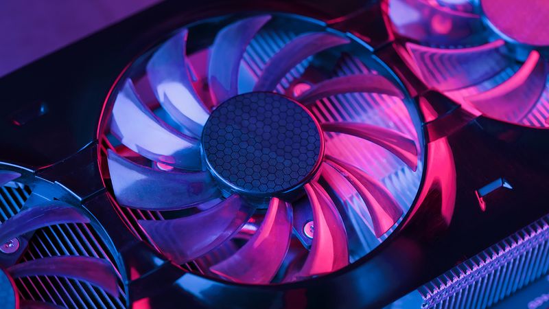
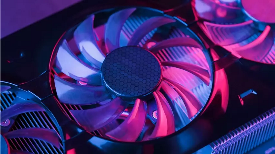
- Fans are useful for active airflow across high-power components such as microprocessors and rectifiers in more complex systems. All components can now be modeled based on the newly created airflow within the enclosure.

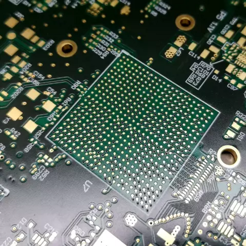
- Increased copper layers within the PCB ground planes can transfer heat away from the device. BGA components may have additional ground pads to extend their thermal ground footprint and remove heat. Additional copper planes on the PCB will increase the ground node’s current capacity to remove additional heat from components.
- Intentional component positioning on a PCBA layout spreads heat sources across the board, preventing hot spots from forming. In conjunction with planes, this helps to ensure a more even temperature distribution.
During the design process, your thermal analysis can identify key areas of temperature risk. Once the temperature extremes are known, proper mitigation solutions can be used to cool the system as part of an iterative design process. For the best manufacturing results and the highest probability of success, discuss your heat mitigation options with your CM partner.