Copper Additive Manufacturing for Heat Exchanger Design
Commercially pure copper is a highly desirable material for heat exchangers and electrical components due to its excellent thermal and electrical properties. While these properties are beneficial for the application, they also turn the process of using copper in AM into a challenge.
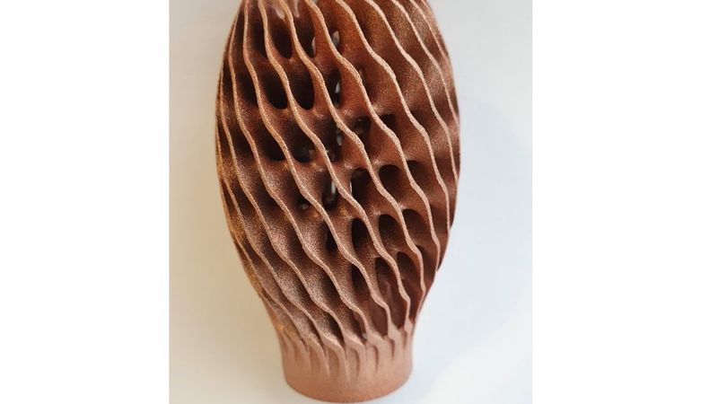
Final part design (Image courtesy of Renishaw)
This article was first published on
ntopology.comIn collaboration with global engineering technologies company Renishaw, this article explores how to overcome this issue and the use of additive manufacturing to produce intricate and complex copper structures for heat exchangers.
Copper 3D Printing Breakthroughs
“Additive manufacturing (AM) is a breakthrough technology that is transforming the manufacturing industry,” explained Kenneth Nai, Principal Engineer at Renishaw. “This digitally-driven process gives engineers the design freedom to create and manufacture parts with complex structures that would never have been possible with traditional machining.”
Traditionally, heat exchangers are made from thin sheets of material that are welded together. The complex geometry of heat exchanger designs makes production challenging and time-consuming. AM systems build parts layer-by-layer, only adding material where needed, to produce lightweight yet complex components, making this process attractive for manufacturing heat exchangers.
“While its high thermal conductivity makes copper the ideal material for heat exchangers, the properties of the material can create challenges when using an AM system,” continued Nai. “The laser sintering of copper powder with an infra-red laser at a wavelength of 1070 nm is difficult because copper is very reflective at that wavelength. Therefore, only a small amount of the laser energy is absorbed into the powder, and a critical threshold of absorption is required to melt the powder together. Combining the high thermal conductivity of copper and the laser energy required, leads to instability and often results in poor mechanical properties of the finished part.”
Renishaw has collaborated with nTopology to demonstrate to manufacturers that, by using the right software and system together, they can reliably additively manufacture intricate structures from copper.
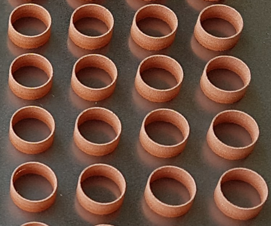
“Combining Renishaw’s RenAM 500S AM system and nTopology software demonstrated an easy method for designing intricate structures suitable for use in heat exchangers and how it can be integrated with Renishaw’s build preparation software, QuantAM,” explained Nai. “At New Mills, our headquarters in Gloucestershire, UK, a RenAM 500S system, with a single 500 Watts laser and 70 micron laser spot size, was loaded with 99.9% pure copper powder supplied by Carpenter Additive. The system was optimized to work with this material. The system was able to manufacture thin walls with a thickness of 0.35 mm and solids with a density over 98 percent, prior to heat treatment in 30-micron layers.”
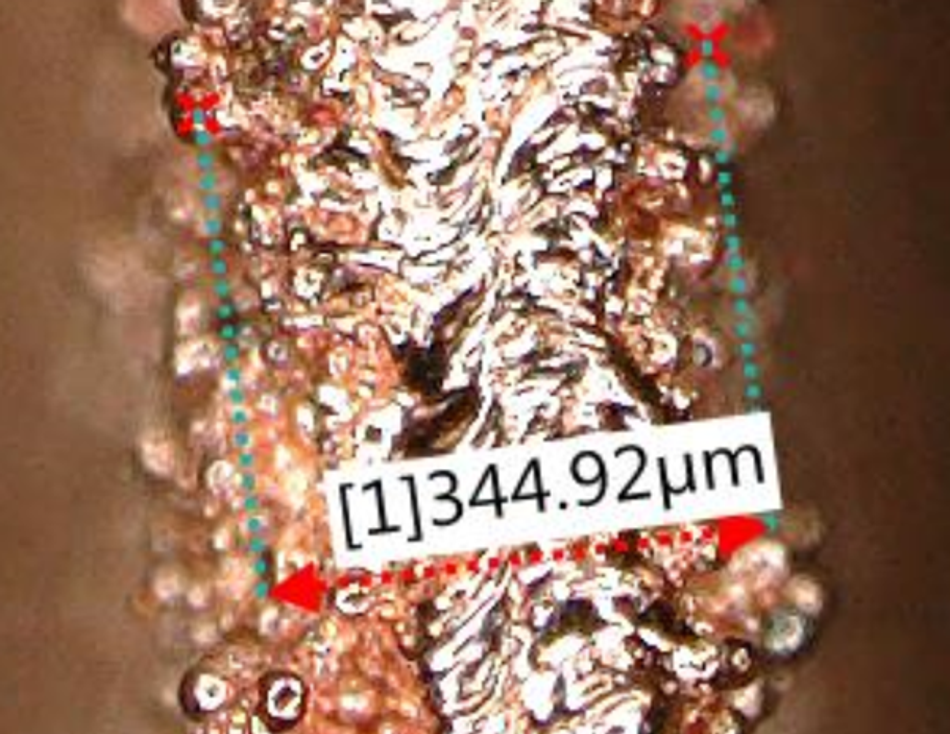
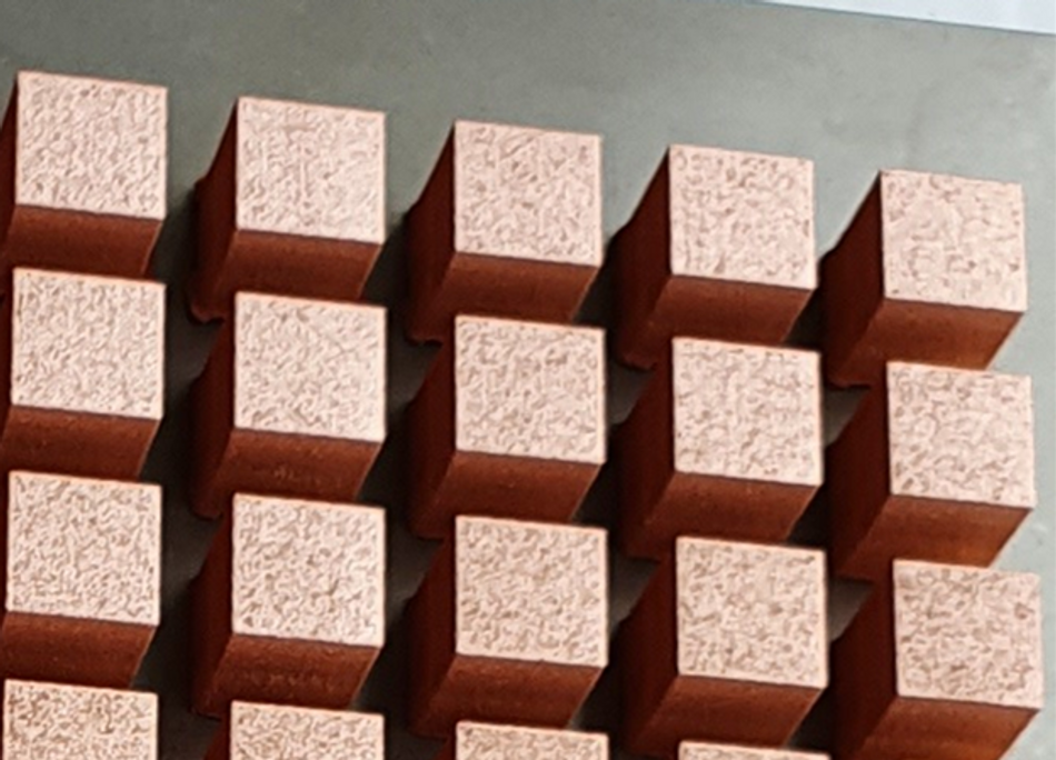
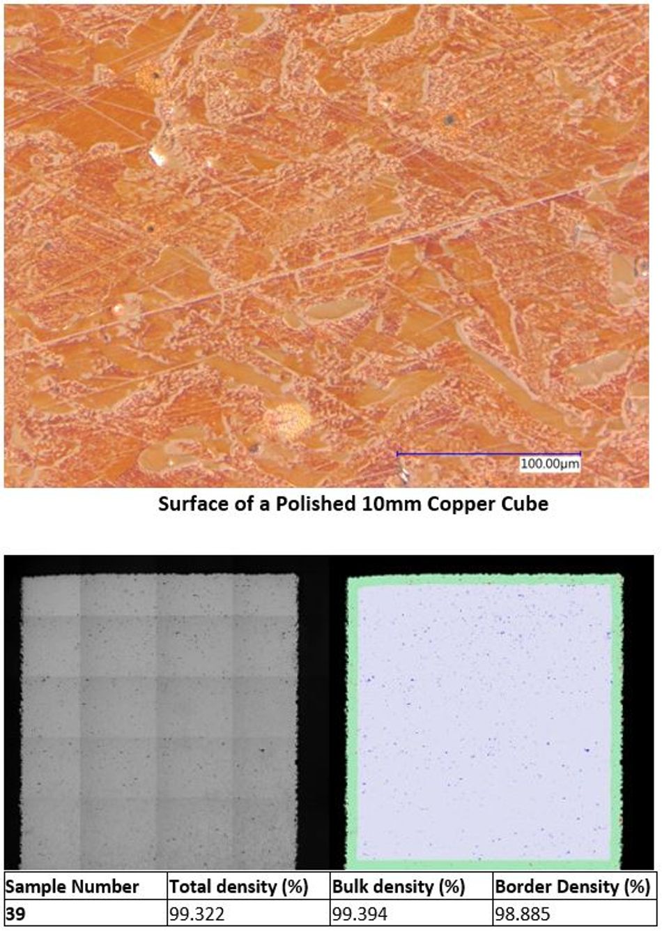
nTopology software was used to generate Triply Periodic Minimal Surfaces (TPMS) that are ideal for heat exchangers as they generally require maximizing the amount of surface area within a given volume.
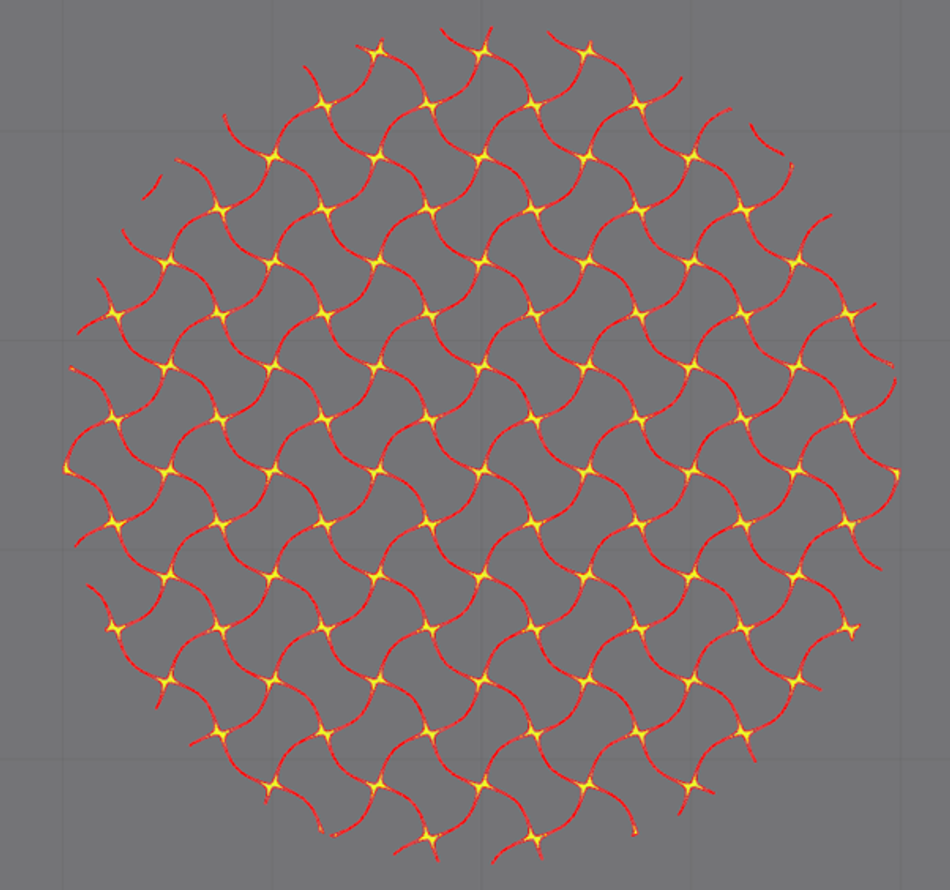
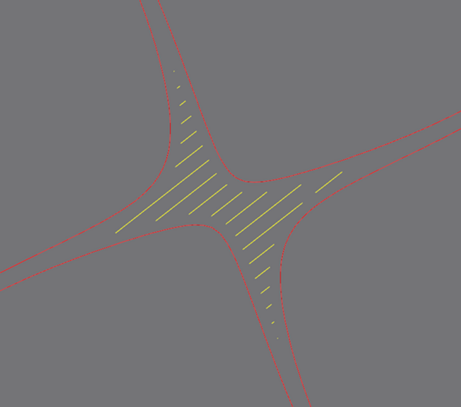
First, a wall thickness of 0.35 mm and cell sizes of 2 mm and 5 mm was used to design these gyroid TPMS structures. Then, nTopology was used to slice the design into 30-micron layers and exported the boundaries and hatches as CLI files. Finally, the CLI files were imported into Renishaw’s QuantAM software to generate the build file for printing by the machine. CLI files remove the need for the traditional STL file format which has many disadvantages when used to describe complex intricate structures like these.
Generating the TPMS Gyroids
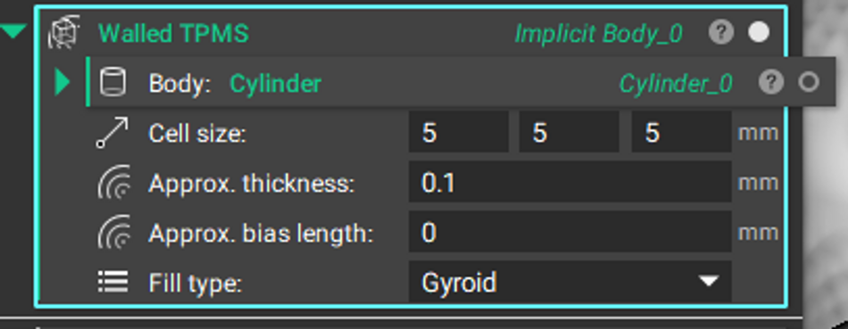
The design process started with using the Walled TPMS Block in nTopology to generate a gyroid with a wall thickness of 0.1 mm and cell sizes of 2 and 5 mm.
The Slicing Step
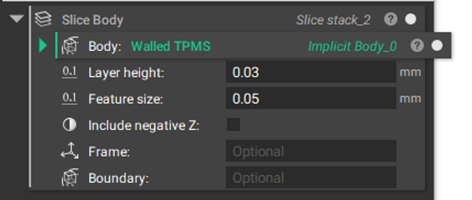
The Walled TPMS Block was then sliced using the Slice Body Block to give the sliced boundaries of the gyroid. A layer thickness of 0.03 mm is used as that is the layer thickness of the machine.

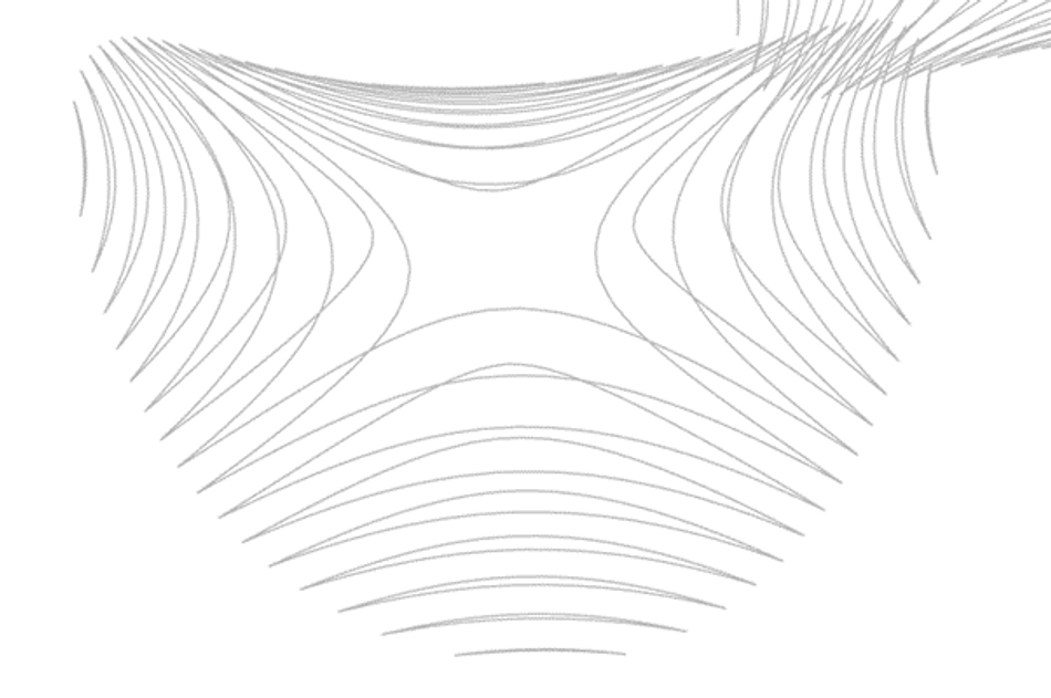
Both the Sliced Boundary and Hatching Stacks were exported as 2 CLI files for print preparation. The CLI files were imported into Renishaw’s build preparation software, QuantAM.
QuantAM adds the machine parameters and generates a file that enables the machine to print the part. Note: Using CLI files removes the need of converting to STL files which are often huge in size and difficult to generate for complex geometries!
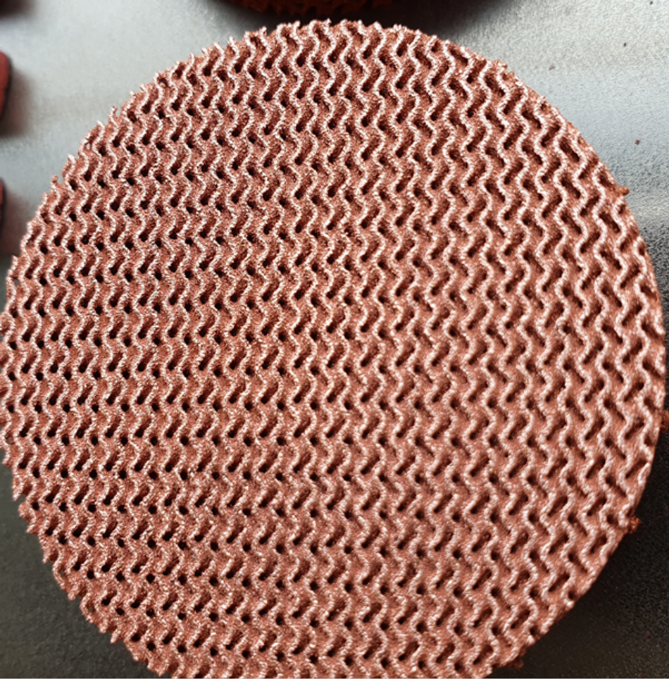
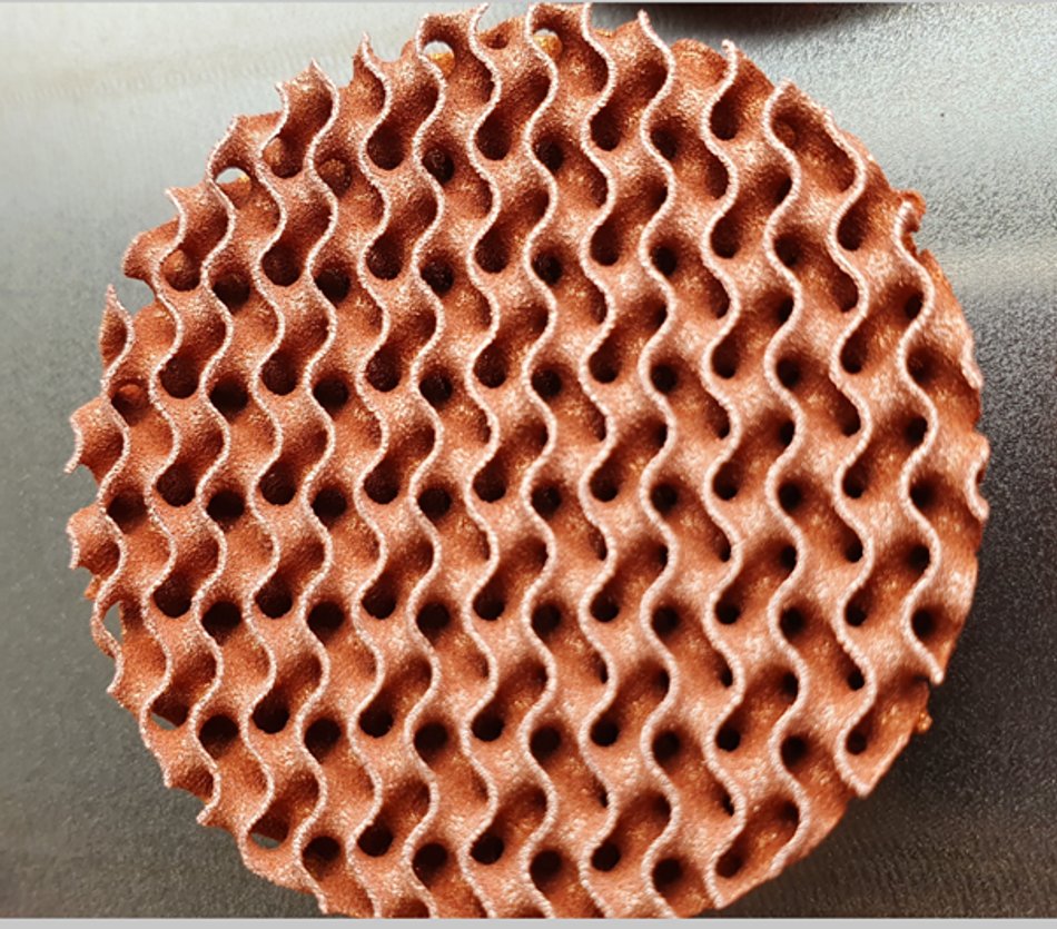
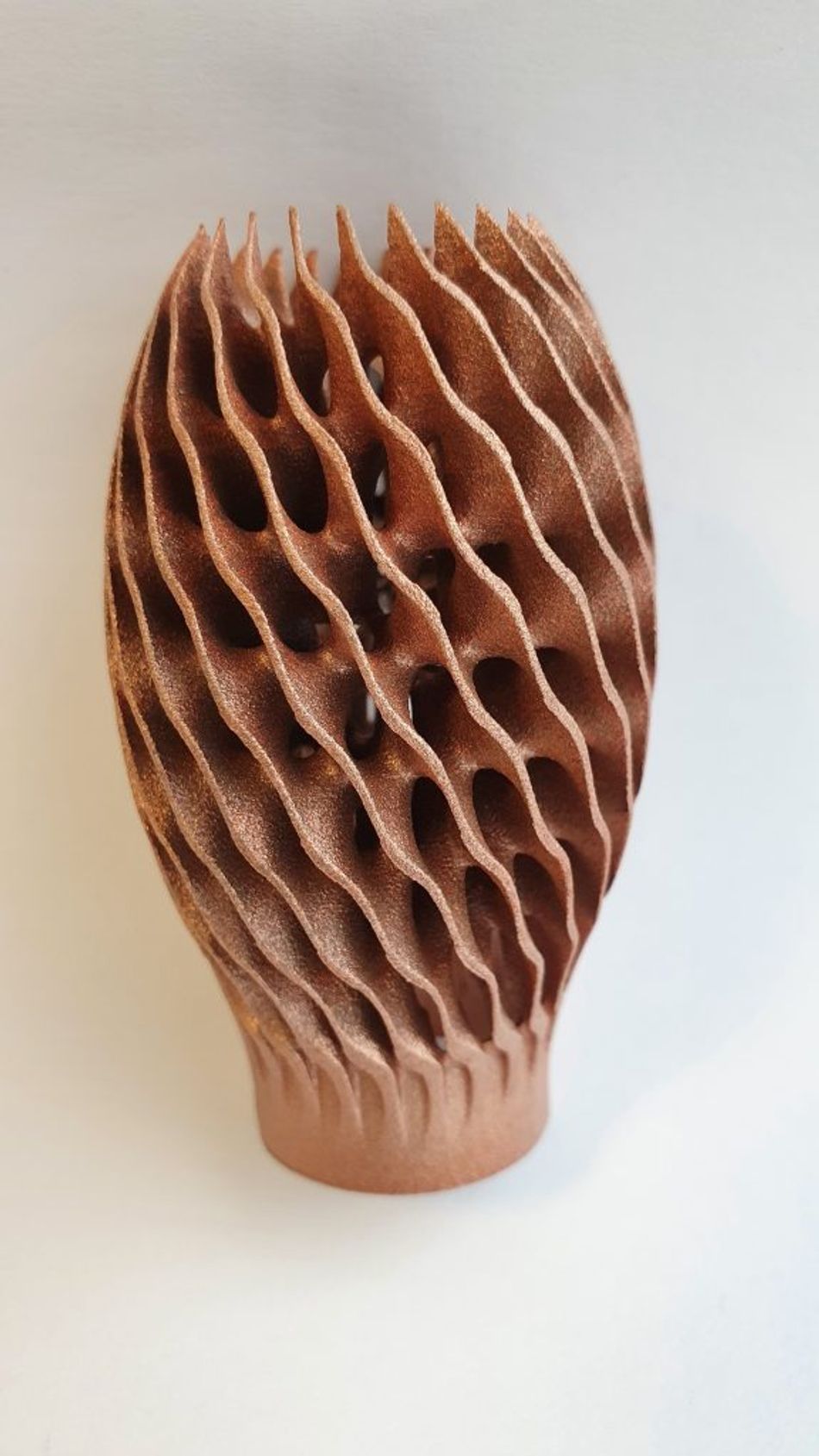 Final part design (Image courtesy of Renishaw) From test samples to end-products
 Final part design (Image courtesy of Renishaw) From test samples to end-products
This article outlined the progress in additive manufacturing of commercially pure copper with the Renishaw AM systems. Heat exchanger design is the most prominent application of this new technology. nTopology equips engineers with the right tools to design advanced heat exchangers that greatly outperform traditional designs and meet the demands of high-performance products.
This article was first published on the nTopology blog.

