Design of surface roughness on CAD of AM lattices using areal surface parameters for better design validation
AM lattices often have a down skin surface roughness different from the up skin one. The workflow shown below enables the design of a virtual “CAD with Designed Surface”. The latter has a surface roughness closer to the actual AM lattice, measured using X-ray Computed Tomography.
This article was first published on
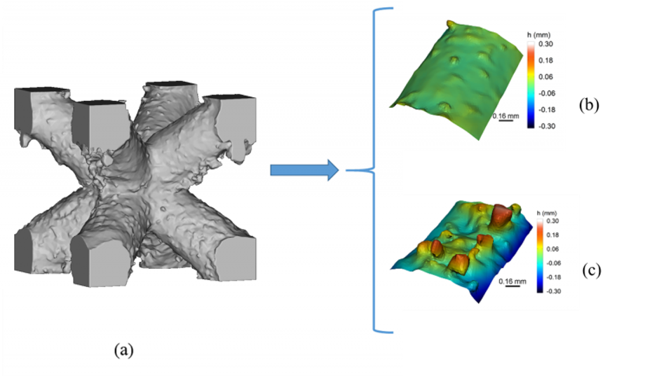
ntopology.comStructural or fluid simulations in the Additive Manufacturing (AM) field are performed a utilizing Computer-aided design (CAD) models of lattice structures that do not contain any information related to the surface roughness. During the Laser Powder Bed Fusion (LPBF) significant surface roughness is produced especially in low overhangs and down skin of lattice structures as can be seen in Fig. 1.

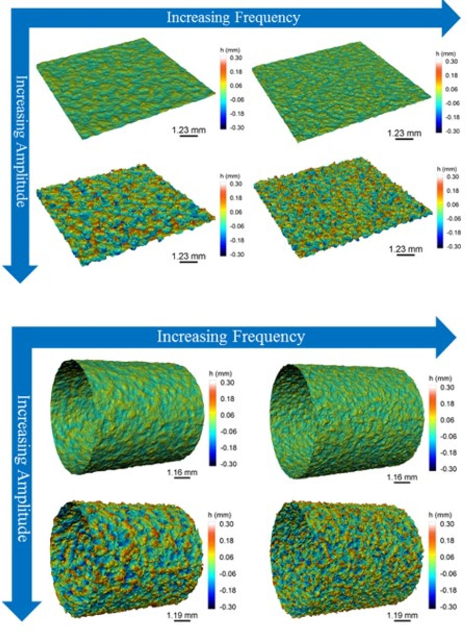
To account for these differences, the expected surface roughness can be designed before the manufacturing process on the CAD of the AM part (Fig. 2), creating a virtual “CAD with Designed Surface” (CADwDS).
In this study, a full factorial Design of Experiment (DOE) has been performed to correlate nTop Platform surface roughness block parameters (frequency, amplitude, seed) with the conventional engineering ISO 25178 areal surface parameters (Sa, Sq, Sp, Sv, Spd). A total of 54 DOE surfaces were generated on both a planar and cylindrical geometry.

The results of the study show a successful correlation between the frequency parameter and the conventional areal surface parameter “Spd” and a separate correlation between amplitude and a developed “max(Sp,Sv)” parameter (also to Sa and Sq). These results demonstrate that it is possible to design surface roughness on CAD models using areal surface roughness parameters in such a way as to replicate the surface that is produced during Powder Bed Fusion.
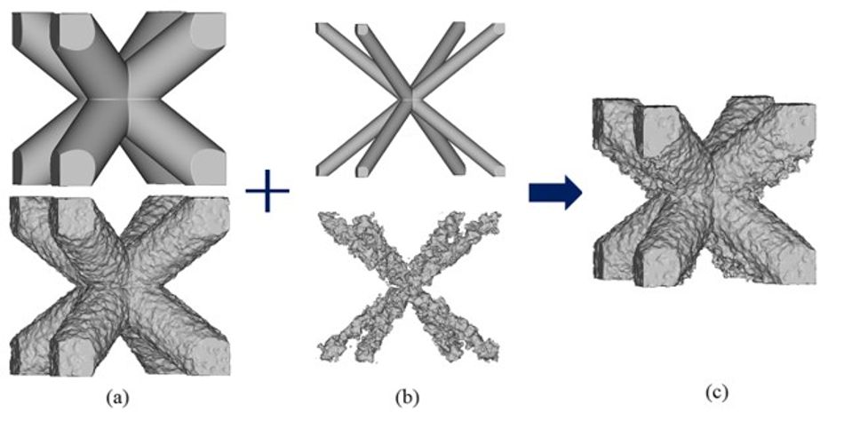
In order to design surface roughness on CAD models of lattice structures two workflows have been developed: one to extract surface roughness from an AM lattice using X-ray Computed Tomography (XCT) as seen in Fig. 1 and another one to design a different upper and down skin surface roughness on a strut-based lattice as seen below.

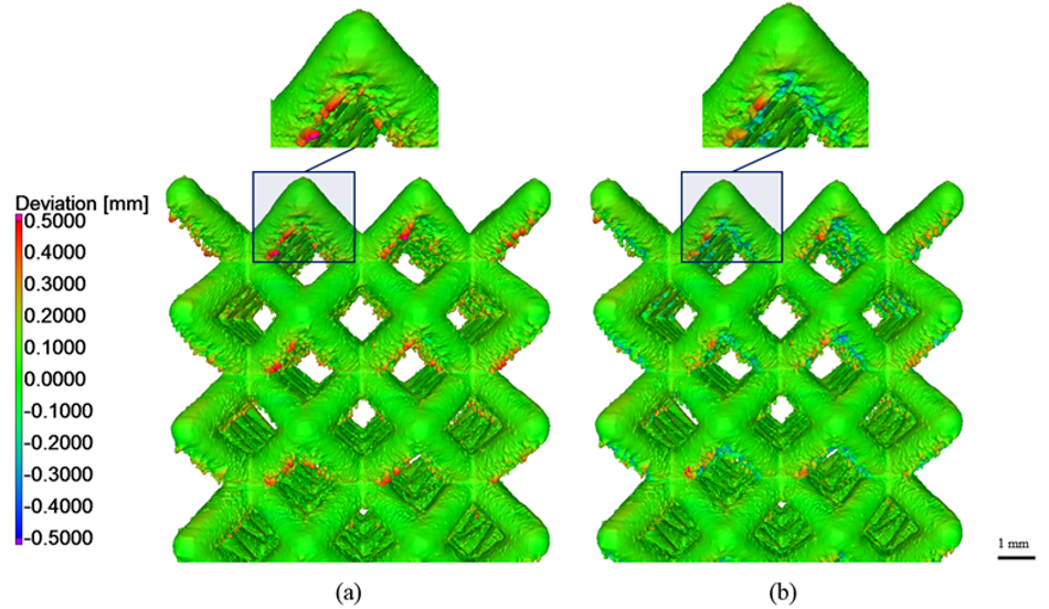
The result was a CADwDS that had a closer surface roughness and smaller mean deviation (Fig.4) to the XCT of the AM lattice compared to the original perfect CAD versus the XCT. More information can be found in my published research paper, Parametrically designed surface topography on CAD models of additive manufactured lattice structures for improved design validation.

In conclusion, the research in this field will enable the design of virtual CAD models that contain a realistic and better expectation of the anticipated defects or deviations prior to the AM process, assisting in the design validation process and cost-effectively assessing different printing parameters, strategies, surface treatments and behavior of AM parts.
This article was first published on the nTopology blog.
