Injection Molding Tolerances
Injection molding part tolerances are crucial, defining the design intent in dimensional accuracy and functionality.
This article was first published on
jiga.ioInjection molding tolerances are the accepted deviations from the exact dimensions that parts are supposed to have in the injection molding process. These tolerances are key for dealing with the natural inconsistencies of turning liquid plastic into solid objects, making sure the final products work as intended and fit well with other parts. Balancing the need for precision with cost considerations is a big part of setting these tolerances.
Take a couple of examples that illustrate the problem:
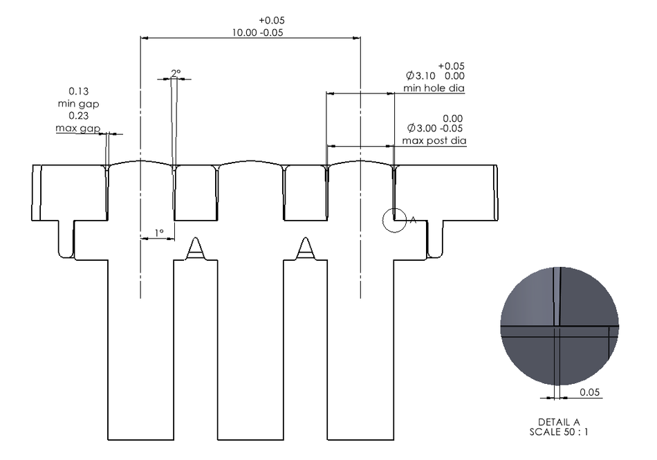
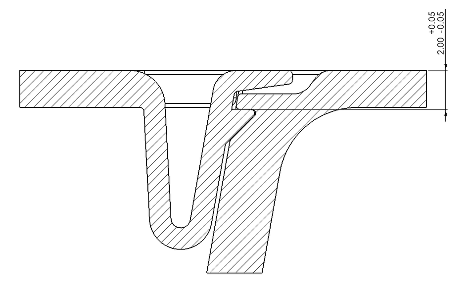
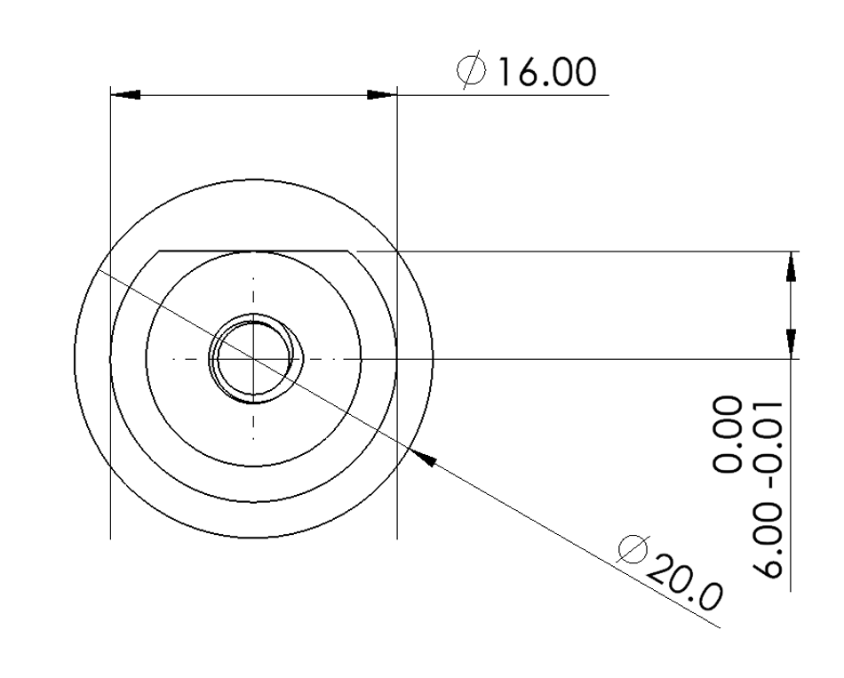
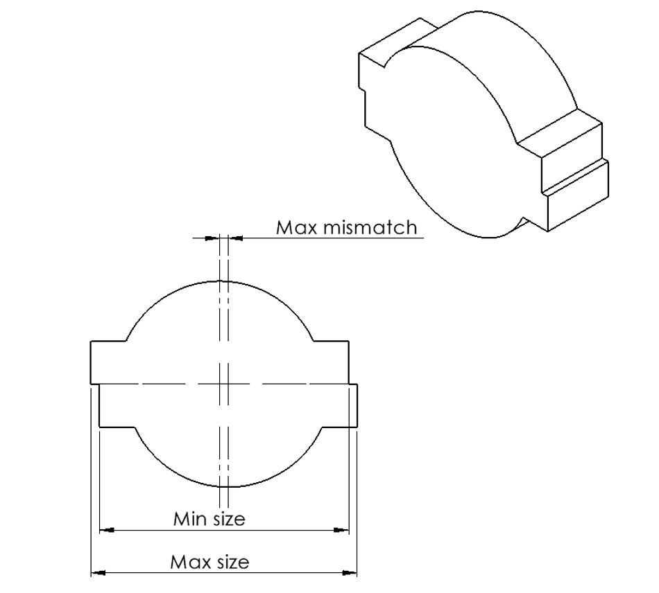
First let's look at a light pipe molded in clear acrylic that needs to fit into holes in a product housing. If the light pipe is oversize, or the hole undersized then there's a risk that the parts won't mate. But if the hole is too big or the light guide is too small, it'll look horrible, because the gap between the light pipe and the housing will be too big! So tolerancing these features to give the required fit is important. Look at these cut-though models to see how we control this.
There are a series of typical steps that drive the tolerancing of these parts:
The outside edges of the housing holes must be flash-free so they cannot be at the part line.
Clean edges are very hard to achieve at the part line and roughness at the edges of these holes will be really visible, illuminated by light leakage.
The edges of the case and light pipe are slightly radiused to make them features as they cannot be hidden, in this mode of design.
The gap must be small but having zero draft angle will make ejection difficult, so the gap cannot be zero.
The light pipe must be able to get into the holes under the worst case condition. This means tight control over both diameters and the distance between centers for the holes and the light guides.
The light pipes will be very ugly if they have a part line on their circumference, so the cylinders must be line of draw and slightly drafted to avoid scuffed surfaces leaking light.
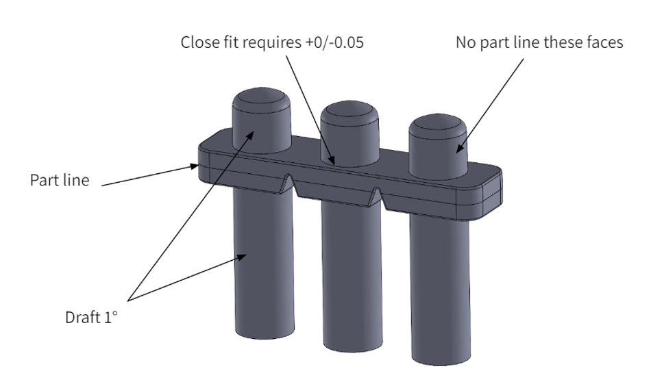
The end result is a small, visible gap that is radiused. Its size is set by the draft angle - this model is set at 1°, a 0.5° will reduce this. General tolerances for these parts can be a more typical +/-0.2mm.
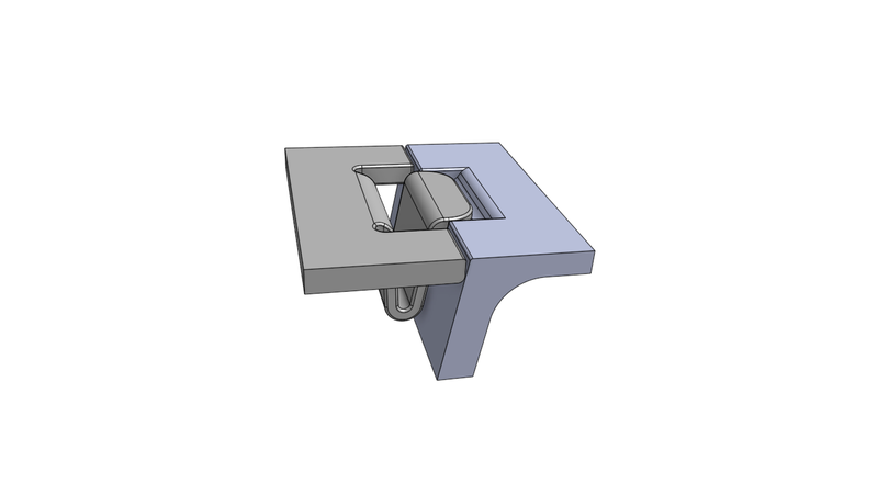
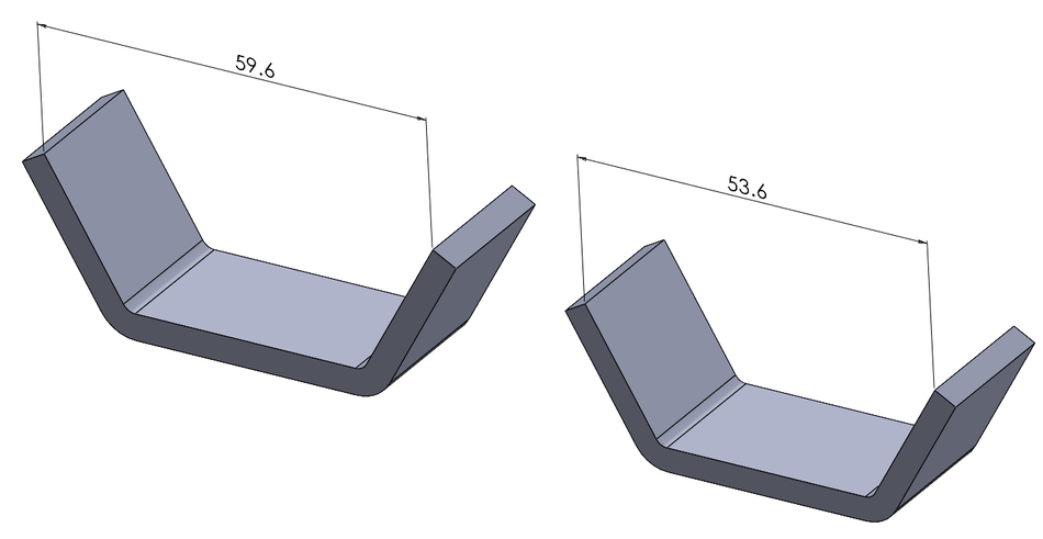
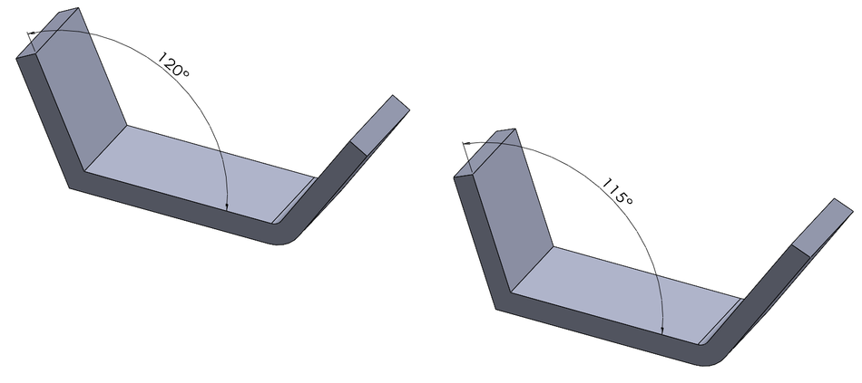
The second illustration is a common and elegant battery door clip, based on a small latch that is sprung on a simple living hinge. The beauty of this mechanism is that there really is only one critical dimension, that defines how the door sits flush with the surrounding surfaces. This high tolerance dimension defines the top face of the slide feature that withdraws to make the latch recess - and the same dimension and tolerance applies to the top face of the latch feature on the live hinge. The live hinge allows everything else to be relaxed tolerances and the clip mechanism flexes to take up the gaps (or compress to match the tight fit).
What are injection molding tolerances?
Injection molding tolerancing describes the allowable (tolerated) maximum deviation from the intended dimensions of any particular feature of a molded part. Molding is a liquid-to-solid process that has inherent precision issues, so understanding how to get the best from the process is important in design and manufacture. Equally, asking too much precision of the process can make life difficult (and expensive).
These tolerances are the main tool for ensuring that the accuracy and consistency of manufactured parts matches what’s needed in the real world. Tighter tolerances (i.e. lower tolerance for deviation) give better assurance that parts meet design specifications and will function correctly within assemblies. If every dimension of every part was exactly to drawing, to umpteen decimal places, the product WILL go together and work! It will also cost a LOT, so we must design to thoughtfully tolerate deviance.
High tolerances minimize the need for additional post-processing or machining. Molding a hole may be accurate enough, but if it needs to be reamed then the cost will go up. Moderate tolerances keep the cost down - but the assembly must be able to accept the variations that result, without failing. It’s critical to strike a balance.
Understanding and controlling tolerances is essential for achieving great products across all industries - automotive, aerospace, consumer products, industrial, medical devices and more anywhere that precision is paramount and parts must fit and function.
Well specified and effectively managed tolerances enhance part performance, streamline manufacturing processes, and contribute to overall product success and customer satisfaction.
Factors Affecting Injection Molding Tolerances
A LOT of factors influence injection molding precision and repeatability, acting in complex and interrelated ways like a matrix of influences in determining the accuracy and consistency of molded parts. Among the influences:
Resin selection
Resin selection is a huge factor affecting tolerances. Thermoplastics have a wide spectrum of shrinkage rates and thermal expansion coefficients, and these directly impact the faithfulness of the solid polymer in reflecting the cavity in which it is formed. You have to carefully consider resin properties like the melt-flow index (the flowrate of the molten polymer under regulated test conditions), viscosity and the micro-and-macroscopic cooling behavior, to grasp how to control dimensional accuracy.
Shrinkage rate
The shrinkage rate defines the percentage decrease in a typical linear dimension as the molten polymer cools to ambient temperature. Understanding and compensating for shrinkage is central to achieving accuracy and repeatability in molded parts. Fundamental material properties like amorphousness/crystallinity, molecular weight, polymer morphology and additive influences all drive shrinkage behavior and must be characterized collectively in specifying the cavity size. Remember, the molding will shrink, so the cavity must be oversized to compensate. How much oversize is a slightly black art.
Shrinkage requires some skill in a) compensating by cavity over-size at tool design and b) packing. These two factors are critical in delivering the required tolerances on key dimensions and this is one of the main drivers of the pressure towards loose tolerances where dimensions are less critical:
a.) When the cavity is virtually cut in the tool bolsters, it is typically made oversize to compensate for the anisotropic shrinkage in the polymer. Shrinkage can be somewhat non-uniform, depending on part geometry AND it is a linear function of length, so small features suffer low distortion due to shrinkage.
b.) When the cavity is filled, sustained pressure at the gate (packing or dwell) will continue to push material into the thicker sections as they cool, compensating for shrinkage and allowing control of tolerances. This is more black-art than oversizing the cavity, as it depends very heavily on part geometry and general wall thickness, but a skilled tool designer and molder team will have ‘seen it before’ and will have good ideas you can draw on for holding precision on critical dimensions.
Wall thickness and transitions
Wall thickness seriously affects tolerances, as thicker sections tend to shrink more than thinner areas during solidification. Non-uniform wall thickness and poorly placed thickness transitions can lead to warping and dimensional inaccuracies.
Factors such as mold design, gate type and placement, injection machine processing parameters and even environmental conditions (e.g., temperature and humidity) can impact tolerances. By carefully controlling as many variables as possible and accommodating material properties and part geometry, tool designers and molders can tighten tolerances and produce high-quality injection-molded components.
Warpage is a particular concern in making precise moldings. Countering this requires experience in design, toolmaking and molding but the effects can be dramatic, particularly where corner transitions are not blended to reduce stresses and fill-flow is turbulent.
Understanding Tolerance Class and Range
Tolerance class in injection molding describes the level of precision or tolerated variation in dimensions specified for a molded part. On a part drawing, it is denoted by letters or numbers associated with a dimension.
ISO 20457:2018 - Plastics Molding Tolerances – Dimensional Tolerances for Molded Parts. This international standard provides guidelines for general dimensional tolerances for plastic molded parts. It outlines the general tolerances based on the type of plastic and the size of the part.
Class A (High Precision), for parts requiring very tight tolerances.
Class B (Medium Precision), for most standard plastic molded parts of moderate precision.
Class C (Low Precision), for parts where loose tolerances are acceptable, often in non-critical applications.
DIN 16901 - Tolerances for Molded Plastic Parts. This is a German standard that categorizes tolerances based on the precision required for the application: coarse, medium, fine, and very fine. It provides specific tolerance values for different dimensions and materials.
Fine Tolerances (F), for high-precision parts.
Medium Tolerances (M), for parts with moderate precision requirements.
Coarse Tolerances (C), for parts where precision is less critical.
Very Coarse Tolerances (V), for parts with minimal precision requirements
ISO 8062-1:2007(en) - Geometrical product specifications (GPS) — Dimensional and geometrical tolerances for molded parts. This is a tolerancing system particularly relevant ot castings and moldings that are machined after first forming.
Tighter tolerances target more precision but require additional tooling complexity, slower processing and post-work steps, delivering considerably higher manufacturing costs. Conversely, a looser tolerance class offers greater flexibility (lower cost) in manufacturing but may compromise part accuracy performance.
The range of tolerances in injection molding typically depends on many factors. Manufacturers must select the appropriate tolerance class and range to meet design requirements while balancing cost and manufacturability. As a rule, a general tolerance of +/-0.1mm on small dimensions is readily achieved, though as the feature size increases this can become challenging. Where necessary, features can be specified to +/-0.05 or even 0.025, but these should be assigned with care and only to dimensions that are actually critical!
Importance of Mold Design in Achieving Tolerances
Mold design plays a central role in achieving high tolerance injection moldings. The design of the mold directly influences part geometry, cooling rate, material flow and shrinkage, all of which have knock-on effects in accuracy.
A well-designed mold includes features such as low-shear/turbulence gating and good gas venting, enough cooling channels and appropriate surface finishes. These elements help minimize warping, shrinkage, voids/traps and other molding defects, helping deliver consistent part dimensions within tolerance.
By optimizing mold design, manufacturers can enhance the quality, repeatability, and cost-effectiveness of the injection molding process while meeting stringent tolerance requirements for the final parts.
Process Control for Injection Molding Tolerances
Process control is central to achieving controlled tolerances in molding. Close monitoring and adjustment of parameters, derived from thorough trialing, will give the best results. Injection pressure, barrel and tool temperature, dwell time and cooling time all influence precision and repeatability.
Through aggressive process control, molders deliver tighter tolerances, reduce scrap rates, and elevate part quality.
Methods to maintain injection parameters
Maintaining injection parameters, once an optimum setup has been derived, involves several methods.
Regular calibration and best-possible maintenance of equipment ensure consistency.
Employing real-time monitoring systems allows quick response to drift in parameters.
High-quality raw materials and appropriate and consistent drying before molding helps a lot.
Optimized tool design contributes to better tolerances.
Implementing stringent inspection and testing protocols, picks up deviation or drift from expected dimensions in real time.
Ensuring excellent machine operator training always improves operation of machinery.
Multiple Components and Tolerance Interplay
Precision and repeatability in injection molded assemblies requires deep understanding of the interactions of components on the product. At its core, it is a primary design issue to:
Understand the component interaction
Make the design tolerant of size variations to the degree that it is possible - loose fits are forgiving of molding variance, exploiting elasticity in design can make features error tolerant.
Understand the molding/tooling issues that affect tolerances and apply the limitations wisely - never tolerance tight for the sake of tightness.
Material selection, part design, mold construction, and process parameters all drive molded part tolerances, through complex interactions. Viscosity and shrinkage rates affect how the material flows and solidifies within the mold cavity, heavily influencing dimensional precision.
Part design considerations like wall thickness and feature geometry also play a heavy role in determining practical and repeatable tolerances.
Mold construction and maintenance ensure proper alignment and functionality, minimizing variability - slider wear impacts critical areas in subtle ways that can be massive.
Process temperatures, pressures and injection speed further refines tolerances, with more subtle effects.
Optimizing each and all of these components can effectively manage and deliver the best practical tolerances in parts.
Tolerance Standards and Measurement
Tolerance standards in injection molding prescribe the tolerable deviation from the intended dimensions in parts. Commonly used standards include:
ISO 20457 specifies general tolerances and ISO 20461 is narrowly specific to linear dimensions. These present guidelines for dimensional variations based on factors such as part size, complexity and criticality.
This delivers a framework for specifying acceptable ranges for features such as dimensions, surface finish, and geometric characteristics. Not all of these have clear tolerancing definitions by numerical value, so they can be assessed by other means.
Established standards allow designers and manufacturers to communicate tolerance requirements clearly and effectively, ensuring that moldings meet design specifications and function reliably.
Methods and tools for measuring tolerances
Measuring moldings is crucial for ensuring quality and compliance with design specifications.
- Coordinate measuring machines (CMMs) use computerized 3D probing to measure part dimensions precisely.
Optical measurement systems analyze camera and sensor data to capture part features and dimensions accurately. These serve in both surface finish and 3D measurements.
- Micrometers and calipers are commonly used for quick and simple measurements of accessible reference dimensions.
Laser scanners provide non-contact measurement of parts, generating precise point cloud data that can be measured virtually.
Profile projectors offer an enlarged image of the part onto a screen for visual inspection and measurements.
Selecting methods and tools to suit a task can validate molding tolerances and assess whether deviations in parts meet the specification.
Comprehensive Design Guidelines for Injection Molding
Design Phase Considerations
Designing parts with tolerance considerations from the outset serves to ensure manufacturability and function.
Maintain uniform wall thickness to prevent warping, sink marks and uneven cooling.
Sharp corners and thick sections produce stress concentrations, so radius corners and blend wall thicknesses.
Gate and vent for optimal flow, shortest flow path, effective packing and good welding.
Define a part line early in the design but be ready to adjust it, when advised by the tool designer.
Incorporate draft angles on line-of-draw faces for easy ejection.
Minimize/combine undercuts and use sliders.
Use ribs and gussets to add strength and stiffness to parts without increasing wall thickness.
Understand the materials shrinkage rates and mechanical properties.
Considering these factors early in the design phase enables mold-adapted parts that meet dimensional tolerance expectations and general quality issues.
Mold Design Considerations
Mold design plays a seminal role in achieving accurate tolerances in injection molding. The more critical dimensions must be specified to the designer to enable a design that ensures more precise replication of these features.
Factors such as gate location, cooling layout, venting and ejector layout heavily influence dimensional accuracy and part quality. Optimizing these aspects minimizes the risk of shrinkage, warping and other issues that compromise tolerance outcomes.
Better quality materials and equipment and more advanced process management greatly enhance the precision and consistency of molded parts.
Conclusion
Injection molding part tolerances are crucial, defining the design intent in dimensional accuracy and functionality.
Resin selection, shrinkage rate, and wall thickness drive tolerance outcomes in a complex and tangled matrix of influences.
Mold design is central to achieving desired tolerances, controlling critical dimensions and features at the expense of non critical areas.
Process control and parameter maintenance heavily influence part outcomes.
Experienced design can minimize tolerance issues early.
Understanding tolerance standards and measurement methods validates outcomes as compliant.
Attention to detail at every stage is essential for meeting tolerance requirements in injection molding. Knowing what can go wrong down-stream is the most essential tool in preventing these effects early, to avoid addressing them later and much more expensively.