5 Key Draft Angle Strategies for Better Injection Molded Parts
In this article, we'll explore what draft angle in injection molded parts is, its benefits, and five key strategies for effectively incorporating it into your designs.
28 Jun, 2024. 4 minutes read
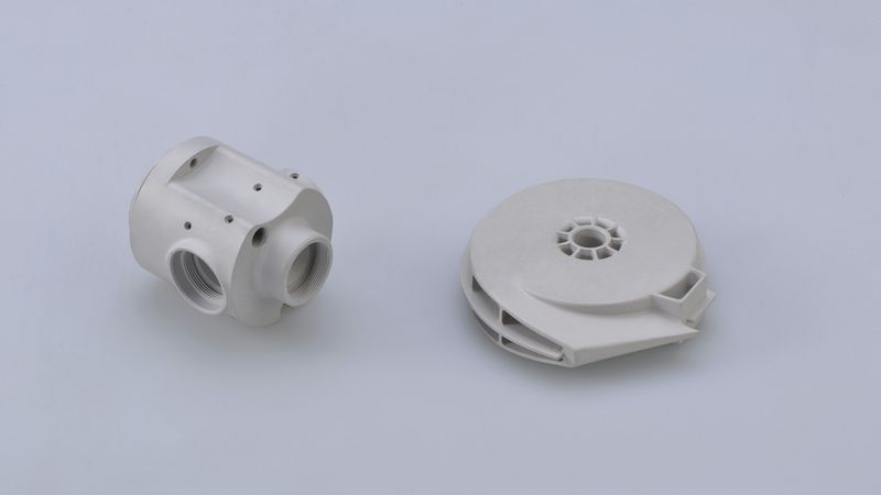
Photo by Mastars on Unsplash
Injection molding is a widely used manufacturing process for producing plastic parts. One crucial aspect of designing these parts is incorporating a draft angle. But what exactly is a draft angle, and why is it so important? In this article, we'll explore what draft angle in injection molded parts is, its benefits, and five key strategies for effectively incorporating it into your designs.
What is Draft Angle in Injection Molded Parts?
A draft angle is a slight taper added to the vertical surfaces of a part design. Plastic injection molded parts must be removed from molds after they cool and solidify, this angle facilitates the removal of the part. Without the drafts, it becomes challenging to remove these parts from molds, causing costly and time-consuming production delays.
Advantages of Adding Draft Angle in Injection Molded Parts?
Beyond facilitating the removal of parts from molds, adding a draft angle to your injection molded parts offers several benefits:
1) Reduces Surface Damage: Minimizes friction during the ejection process, protecting the part's surface.
2) Ensures Surface Uniformity: Maintains the integrity of textures and finishes.
3) Prevents Deformation: Reduces part deformation caused by unsmooth ejection.
4) Decreases Mold Wear: Lessens wear on molds, lowering the risk of damage.
5) Shortens Cooling Time: Simplifies ejection setups, potentially reducing overall cooling time.
5 Key Draft Angle Strategies for Better Injection Molded Parts
1. Essential Rules for Draft Angles
1) The draft angle is generally 1 to 2 degrees.
2) Parts with high dimensional accuracy requirements should use smaller draft angles.
3) The draft angle for convex features should be larger than that for concave features to facilitate ejection.
4) For parts with thicker walls, the molding shrinkage increases, so the draft angle should be larger.
Feature Depth | Minimum Thickness/Draft Angles | |||
0.25 in. | 0.040 in./0.5° |
|
|
|
0.5 in. | 0.040 in./1° | 0.060 in. /0.5° |
|
|
0.75 in. | 0.040 in. /2° | 0.060 in. /1° | 0.080 in. /0.5° |
|
1 in. |
| 0.060 in. /2° | 0.080 in. /1° | 0.100 in. /0.5° |
1.5 in. |
|
| 0.080 in. /2° | 0.100 in. /1° |
2 in. |
|
|
| 0.100 in. /2° |
2. Draft Angles for Injection Molded Materials and Structures
Materials with higher hardness require larger draft angles. Surfaces that are not smooth also need larger draft angles. Additionally, parts with complex shapes, higher shrinkage rates, and reinforced plastics should all use larger draft angles. Please refer to the table below for draft angles of some common materials and features.
Material | Minimum Draft | Recommended Draft |
0° | 1° | |
0.5° | 1.5° | |
0.5° | 1.5° | |
1° | 2° | |
1.5° | 2° | |
Ribs | 0.25° | 0.5° |
Textures | 3° (light textures) | 4-5° (heavy textures) |
3. The Degree and Direction of the Draft Cannot Affect the Functional Realization of the Product
When two parts have a motion relationship, the size and direction of the draft at the mating point need to be considered so as not to affect the realization of product functions. The picture below is the structural cross-section diagram of the button and panel on an electrical product. The function of the button is to trigger the electrical switch, and it is necessary to ensure that the button will not get stuck and shake during movement. Therefore, the upper and lower gaps at the mating surface are required to be consistent, and the movement path of the button is a linear motion. In the original design, the upper and lower gaps at the mating surface of the button and the panel are inconsistent. The button will shake during movement, and it might get stuck in the panel in serious cases, causing the button to fail to trigger the switch. In the improved design, the upper and lower gaps at the mating surface of the button and the panel are consistent, the movement path of the button is vertical, and the button will not get stuck.
4. Design Side Cores
A draft angle typically helps in the removal of the part from the mold, but if functionality dictates that a surface must be vertical or have specific orientation that does not allow for a draft, a side-action core (or side cores) must be incorporated into the mold design.
Side-action cores are mechanisms that slide into the mold cavity to form undercut features or vertical faces that are not parallel to the mold opening direction. It's impossible to realize with a straightforward open and close motion of the mold. However, incorporating side-action cores makes the mold design more complex and significantly increases the cost.
5. Leverage DFM Analysis
PRWORLD offers free but in-depth DFM analysis for every part design. By simply uploading your 3D CAD model, you'll gain valuable design feedback, including design optimization suggestions, including suggested modifications to improve moldability and ensure quality production. You can also benefit from the expertise of our engineering team and avoid common design pitfalls such as inadequate or missing draft angles, reducing production time and cost.