How to Combat Signal Integrity Issues in High-Speed Drone PCBAs
Drone flight is energetically expensive, especially for smaller devices. To manage this, drone PCBAs are designed to be compact, dense, and fast to pack more functions into a smaller space.
13 Jun, 2024. 7 min read

Drones rely on high-quality PCBAs
This article was first published on
www.macrofab.comHow to Combat Signal Integrity Issues in High-Speed Drone PCBAs
Drones are everywhere. They’re changing the way we work and live, from keeping borders safe in the U.S. to fighting the COVID-19 pandemic. But what makes a drone work reliably?
At the heart of every drone is its high-speed Printed Circuit Board Assembly (PCBA), a critical component that dictates the device’s performance and reliability. However, a PCBA with a suboptimal design can suffer from poor signal integrity (SI), leading to reflections, crosstalk, and ground bounce. These issues can compromise the circuit’s stability and overall performance.
Reflections can cause erratic flight behavior or even loss of control caused by glitches and errors in received signals. Crosstalk introduces unwanted noise into critical signals, interfering with sensor data or motor control commands. Voltage fluctuations caused by ground bounce can disrupt power delivery and potentially lead to unexpected shutdowns or malfunctions. In short, poor SI
jeopardizes the stability and smooth operation of the entire drone.
Given the slim margin for error, it is crucial for circuit designers to understand the nuances of signal integrity within drone PCBAs. This article explains what signal integrity is, why it matters to achieving quality PCB fabrication, symptoms of poor SI, and how using simulation tools can fix these issues early on in the PCB layout process.
Understanding Signal Integrity in Drones
In digital systems like drones, information moves between components using signals that are basically voltage levels representing binary “0” or “1”. Signal integrity focuses on the quality and timing of signals during a system’s data
transmission.
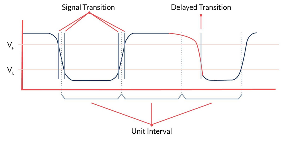
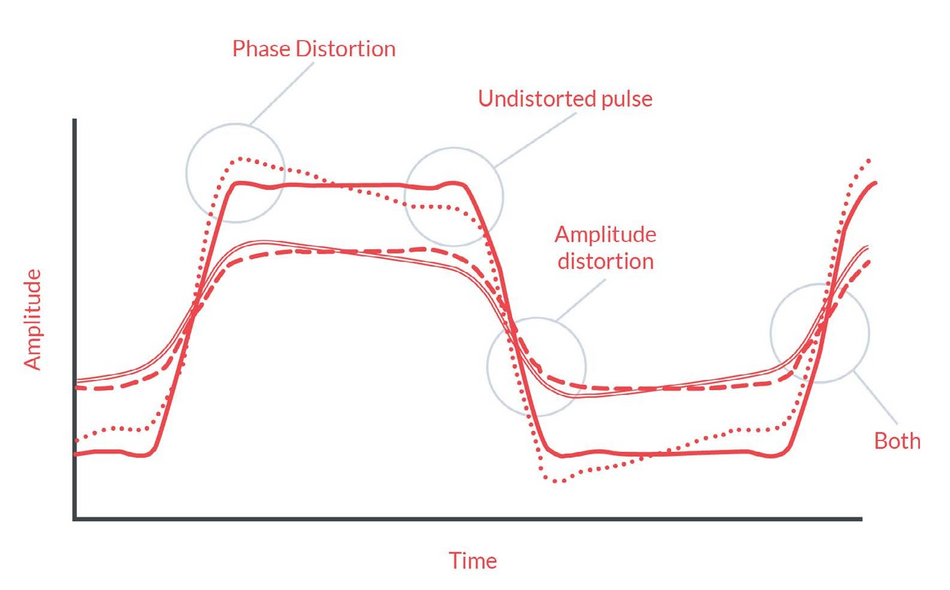
A digital signal with good integrity maintains the correct levels—both for voltage amplitude and timing. Amplitude integrity ensures that the signal’s voltage waveform is accurate and is within the required range for the receiver to interpret it correctly. Time integrity ensures that the signal’s switching edges arrive at the receiver’s input within the appropriate time frame.

Interconnects are the conductive paths these signals travel from the source component to the destination component. They include everything in the path: packages, solder balls, connectors, circuit board traces, cables, and component leads.
The main challenge with signal integrity comes from interconnects’ physical properties, like resistance, capacitance, and inductance. The resistance in the interconnects drops voltage levels, weakening signals by the time they reach the receiver. Also, at high frequencies, the interconnect’s capacitance and inductance cause crosstalk and electromagnetic interference (EMI).
As such, in PCBA design for drones, interconnects are complex frequency-dependent parasitic elements. Under certain conditions, their properties can distort or weaken signals especially in high-speed data transmission, posing a challenge for maintaining signal integrity.
Common Signal Integrity Issues in Drone PCBAs
Signal integrity quality in drone PCBAs directly impacts the bit error rate during data transmission. In turn, this affects a drone's performance. Common causes of poor signal integrity include:

- Crosstalk: This occurs when a signal from one conductive path unintentionally affects another, mainly from capacitive or inductive coupling in the transmission paths. Crosstalk can lead to incorrect logic switching on the quiet trace and alter the timing on active traces.
- Reflections: These happen when electrical currents in PCB traces, which have a specific direction, encounter a change in impedance in the transmission path. This mismatch can cause part of the signal to bounce back, interfering with the incoming signal. Reflections can lead to false clock triggering, increased jitter, and more unwanted emissions from the PCB, all of which degrade the drone's performance.
- Ground Bounce: Sometimes referred to as simultaneous switching noise (SSN) or delta-I noise, ground bounce happens when the ground voltage in a circuit board temporarily spikes. This is due to the inductance in the circuit paths or the inductance from the components' leads when multiple signals switch on or off at the same time. It causes signal distortion, wrong signal reading, and slower data transmission.
Drone PCBA Design Challenges Causing Poor SI
Flight is energetically expensive, especially for smaller devices. This is mainly because of the challenges that come with making vehicles smaller. Smaller sizes mean motors are less powerful for their size, mechanical parts like gears and bearings become less efficient as a result of more friction, and air resistance affects them more due to changes in airflow characteristics (Reynolds numbers).
To manage these issues, drone PCBAs are designed to be compact, dense, and fast to pack more functions into a smaller space. They also use multi-layer boards to improve routing. But, this necessary design approach also makes them more likely to have signal integrity problems.
Here are some drone PCBA design challenges:
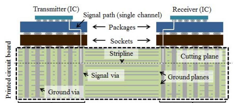
High-Speed Multilayer PCBs: Multilayer PCBs in drones, designed for high-speed signal transfer, include vias that connect different PCB layers. At high frequencies, these vias can introduce impedance mismatches, leading to signal reflections.
Layer Count and Thickness: The complexity of drone PCBAs often requires a high layer count, which thickens the PCB. This thickness increases via heights, increasing insertion losses and degrading signal strength and quality.
Miniaturization and Crosstalk: Drone PCBAs are densely packed and miniaturized, amplifying crosstalk effects. The proximity of traces increases the likelihood of signal interference from adjacent traces.
Heterogenous systems: Drones are heterogeneous systems, meaning they comprise various devices each with its own power, current, speed, and noise requirements. To accommodate these, PCBA layers are often split for separate power supplies. While splitting planes can improve the power/ground network quality, the slots introduced to separate the planes can create undesirable radiated emissions and reflections.
Identifying Symptoms of Poor Signal Integrity
When drone PCBAs suffer from signal integrity (SI) issues, several telltale signs can emerge, indicating that the design might not be as robust or reliable as required. Key indicators include:
- Compliance Test Failures: Drones failing to meet required compliance standards often indicate underlying signal integrity issues.
- Inconsistencies After Component Changes: A drone that initially performs well but starts showing issues after swapping out IC suppliers or board fabricators.
- Sensitivity to Environmental Factors: If a drone's PCBA shows reduced performance when exposed to different power supply conditions or temperature changes, it could be a symptom of poor SI. Good design should ensure stability across a range of operational conditions.
- Lab vs. Field Discrepancies: A design that works well in the controlled environment of a lab but becomes unreliable or intermittent in real-world conditions is a classic symptom of SI issues.
Want to know more about addressing signal integrity problems? Read PCBA Signal Integrity Problems: Ten Factors to Consider now.
Addressing Specific Challenges
While it is impossible to eliminate all SI issues caused by crosstalk, and reflections in a drone PCBA, there are effective strategies that can significantly reduce these problems.
Reducing Crosstalk:
- Space out components from I/O interconnects and areas prone to data corruption.
- Route critical traces away from each other instead of in parallel.
- Decrease the distance between signal traces and their ground references.
- Ensure impedance matching for critical signal traces.
- Avoid using shared return pins in packages and connectors.
Reducing Reflections:
- Match and terminate transmission lines with their characteristic impedance to prevent mismatches.
- Keep via stub lengths as short as possible.
- Utilize stack-ups that position traces close to their reference planes, optimizing signal return paths.
- Select the right via dimensions. Larger diameters can cause more impedance discontinuity, leading to increased reflections and insertion loss, while longer vias might reduce reflections but increase insertion loss.
Transmission Paths with 90° Turns:
Routing transmission lines to components may require turning the line. At high-frequencies, sharp 90-degree turns can cause signal reflection. Instead of one sharp turn, it's common to use two smaller 45-degree turns to ease the bend.
Differential Pairs:
When using differential lines in drone PCBA designs, keep the two lines symmetrical. They should be the same distance apart and have the same length. If they're not equal, it can cause problems like ground bounce. To fix length differences, add a zigzag pattern to the shorter line near its start. This keeps the signals in sync across the PCB.
Fibre Weave Effect:
The fiber weave effect occurs when routing signals on fiber-based substrates like FR-4, where one trace might run over fiber and another over epoxy. The different dielectric constants of these materials can cause discrepancies in electrical length from simulated predictions, especially in differential lines and buses at frequencies above 5 GHz.
To mitigate this, routing lines in a shallow zigzag pattern, about 10 degrees, can help even out the variations by crossing over both fiber and epoxy. Another solution is using isotropic substrates like Rogers' TMM, which don't have this issue, though they are more expensive.
Are you building drones for the defense industry? Read Understanding and Implementing Mil-Spec Standards in PCB Assemblies now.
Simulation and Validation
Using simulation effectively can help pinpoint signal integrity issues in drone PCBAs. Once these issues are identified, the layout can be optimized to enhance performance, and appropriate termination methods can be applied to mitigate signal integrity's impact.
Simulation tools enable early focus on signal integrity, leading to the development of high-performance, reliable, and cost-effective products. This proactive approach speeds up time to market, secures a competitive edge, and reduces the need for extensive prototype debugging, enabling quicker transitions to future projects.
Simulation tools fall into three categories:
Mathematical Tools: These utilize equations and graphs to model digital transmission systems. Examples include Matlab, MathCad, and Mathematica, offering a theoretical approach to signal behavior.
Analog Simulation Tools: These create and simulate a schematic representation of the circuit. Tools like Spice, HSpice, and PSpice are notable for their schematic-based analyses.
Specialized SI Simulation Tools: Designed for high-speed digital circuit analysis, these tools support both pre-layout exploration and post-layout verification. They assess signal quality and compliance with performance margins for various interfaces, including DDR and high-speed serial channels. Examples include HyperLynx and Cadence.
Conclusion
Signal integrity issues can cause product failures or damage components, leading to failures more often after the product is in use rather than during testing. This results in costs for replacing products and losing customer trust.
To fix signal integrity problems, it's important to first figure out why they're happening. Then, use every available tool to find and check the best solution.
By designing and simulating effectively early on, you can weigh the performance against the cost before it's too late, saving time, reducing risks, and cutting costs.