Robot Emission Suppression Measures
Noise suppression includes both emission and immunity suppression, and various measures are in place in robots to prevent malfunction due to immunity.
22 May, 2024. 14 min read
This article was first published on
article.murata.comIntroduction
Robots can be broadly classified into industrial robots and service robots. However, with the exception of the European region, no public noise regulations have been applied to such robots.
At the same time, a committee of the CISPR noise standards body is considering noise specifications for application to robots.
As of 2023, the noise specifications are still under consideration, and the first version is expected to be released to the public in 2024 at the latest.
Information has been published on the Internet that the CISPR committee is considering applying CISPR 11 as the noise specification for application to robots.
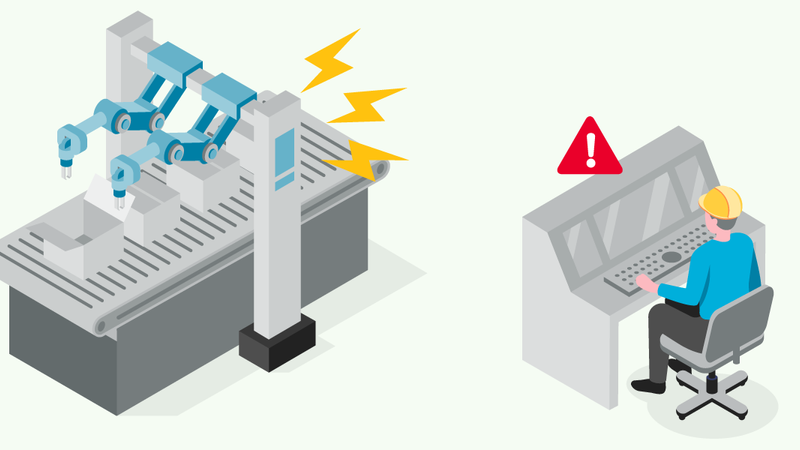
Noise suppression includes both emission and immunity suppression, and various measures are in place in robots to prevent malfunction due to immunity. At the same time, it is thought that emission suppression, which was previously not considered a problem, will become a key point due to the new regulations. Therefore, this article will explain the key points of robot emission suppression.
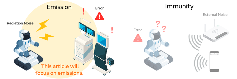
This article introduces suppression methods for robot emissions using case examples.
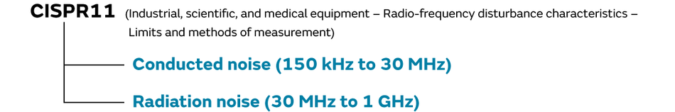
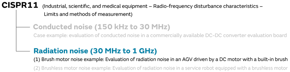
Under the current CISPR 11 emission regulations, equipment is required to have conducted noise evaluated at between 150 kHz and 30 MHz and radiation noise evaluated at between 30 MHz and 1 GHz.
Because standards for robot noise regulation have not been set, the details of the noise regulations may change.
Radiation noise evaluation of commercial robots
Radiation noise measurement and evaluation
In this emission noise evaluation, we used a CISPR 11 radiation noise measurement environment as a reference to measure the radiation noise of a commercially available articulated robot set.
Furthermore, the robot operated any single joint (repeated left-right motion).
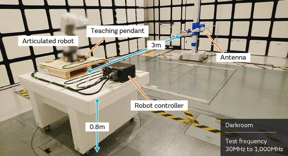
We evaluated the radiation noise.
Two noise tolerances are set in CISPR 11.
Here, Class A covers equipment that is not directly connected to a low-voltage power grid (interpreted as a commercial AC power supply network). For example, the case where AC power is supplied to equipment through a cubicle or other high-voltage receiving equipment. By contrast, Class B covers equipment that is directly connected to a low-voltage power grid (interpreted as a commercial AC power supply network). This would be the case where AC power is supplied in a shared pole-mounted transformer or other public distribution network.
Articulated robots are thought to be used mainly in factories. However, the radiation noise of the commercial robot prepared for this evaluation ended up exceeding the CISPR 11 Class A tolerances, and we found that it did not satisfy CISPR 11, which will become the basis of the standard applied in the future.
Because there are currently no noise regulations applied to robots, this is not a problem under these conditions. However, it is thought that new forms of noise suppression will be needed when the future noise regulations are applied.
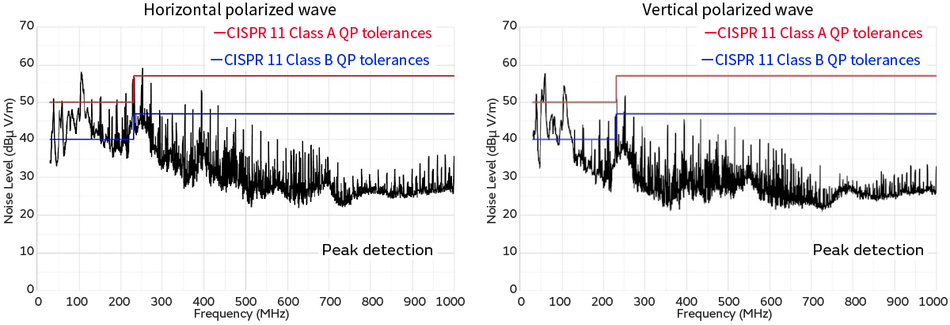
- A needle-shaped noise spectrum was observed.
Investigation of the radiation noise mechanism
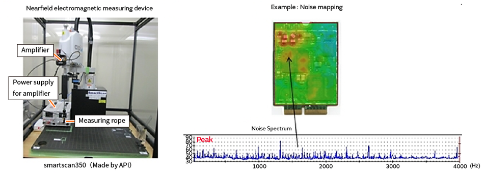
We investigated the radiation noise mechanism using the following methods.
(An example of the investigation that was carried out)
- Noise source investigation
Used a magnetic field probe and electric field probe. *Investigated the field distribution
Searched for locations where a spectrum similar to the trend of radiation noise generation is observed. - Noise-conducting path
Measured the conducted noise of the signal line and power supply line. Used a magnetic field probe and electric field probe.
Measured whether the noise generation trend changes depending on whether the cable is connected. - Noise isolation (radiation antenna investigation)
Separately shielded the equipment. Used a shield box and shield fabric.
Attached a ferrite core to the cable.
Tried changing the operation mode.
As a result of investigating the radiation noise generation mechanism of the purchased articulated robot, we learned the following. The noise source was the switching noise of the DC-DC converter module. The switching frequency of the DC-DC converter is 470 kHz.
There are three noise-conducting paths. The first path conducted switching noise to the negative line of the DC-DC converter output. The negative line was connected to the controller housing, and the switching noise was conducted to the housing.
The second path conducted noise to the housing due to the fact that the crystal heat dissipation plate of the DC-DC converter (heat dissipation plate that the switching noise is coupled to) touches the housing.
The third path conducted noise to each cable connected to the control board (AC power supply, motor, encoder, and teaching pendant cables) with superimposed switching noise.
The antennas leading to external radiation were the controller housing and each cable.
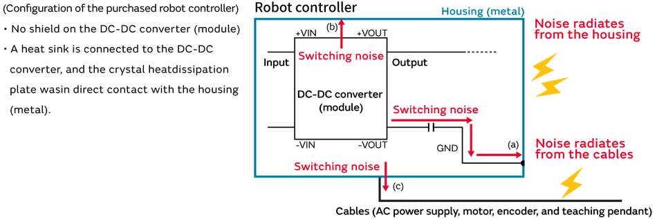
- Noise source: DC-DC converter (switching noise)
- Paths:
(a) Conducted from the output negative line of the DC-DC converter to the housing
(b) Conducted from the crystal heat dissipation plate with coupled switching noise to the housing
(c) The control board switching noise was conducted to each cable - Radiation antenna: robot controller housing and each cable
Suppressing the radiation noise of the robot requires that the noise not be conducted to the controller housing and each cable. As shown in the figure below, it is believed that shielding the DC-DC converter module and inserting a filter in the noise-conducting path is an effective approach.
However, because it is difficult to shield the DC-DC converter due to its construction (unable to completely remove the noise that is coupled to the crystal heat dissipation plate with a retrofitted shield, and it inhibits the heat dissipation, which causes the DC-DC converter to malfunction due to heat), even if measures are carried out for (a) and (c), noise is conducted along path (b), so we were unable to verify the noise suppression effect.
To carry out a measure for (b), it is believed that the wiring pattern and the DC-DC converter module selection must be reviewed along with reconsideration of the method of heat dissipation, and it was determined that there are limits to retrofitted noise suppression.
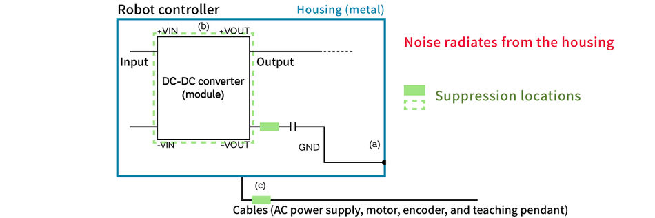
- Suppression proposal: do not conduct the switching noise to the housing and various cables
(a) Noise filter (ferrite beads, etc.) on the output negative line
(b) Shield the DC-DC converter *Do not allow noise to couple to the crystal heat dissipation plate
(c) Noise filter on each cable (common mode choke coil, ferrite beads, etc.)
Summary
Because we could not sufficiently shield the radiation from the DC-DC converter module in this evaluation, we were unable to verify the effect of inserting a filter. However, the key points for selecting a filter are shown in (1) through (3) below.
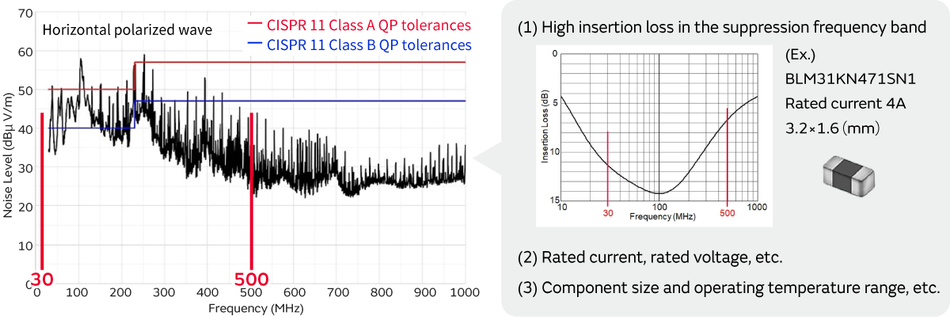
Because robot radiation noise is prone to becoming a problem in many cases between 30 MHz and 500 MHz, an effective approach is to propose a noise filter that focuses on the frequency band.
Thus far, we have introduced a case example of radiation noise suppression using a commercially available articulated robot, but it is expected that there will be various other case examples in which noise becomes a problem.
Here, we introduce three case examples of noise problems that are expected in robots.
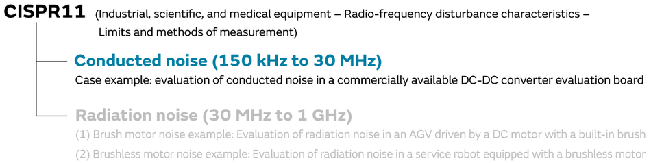
Pseudo-robot emission suppression (conducted noise)
Case example:Evaluation of conducted noise in a commercially available DC-DC converter evaluation board
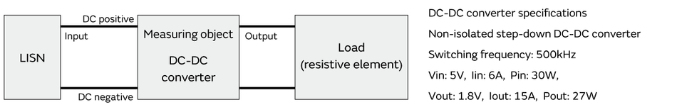
The conducted noise regulated by CISPR 11 is measured with a common mode voltage leaking into an AC power supply line.
Here, it appears that the noise conducted to the AC power supply line is often caused by the switching of the DC-DC converter.
We used the DC-DC converter evaluation board to evaluate the noise.

The measured conducted noise is as follows. A noise spectrum was observed at frequencies that are a multiple of the switching frequency of 500 kHz. There is noise that exceeds the noise tolerances for CISPR 11 Class A Group 1 (industrial environment). This result is not unusual, and in equipment that does not suppress noise (switching noise) caused by DC-DC converter switching, there are many cases in which the switching noise is conducted to the AC power supply line and causes problems.
When public noise standards are applied to robots going forward, it will become necessary to suppress noise that is conducted to the AC power supply line in robots.
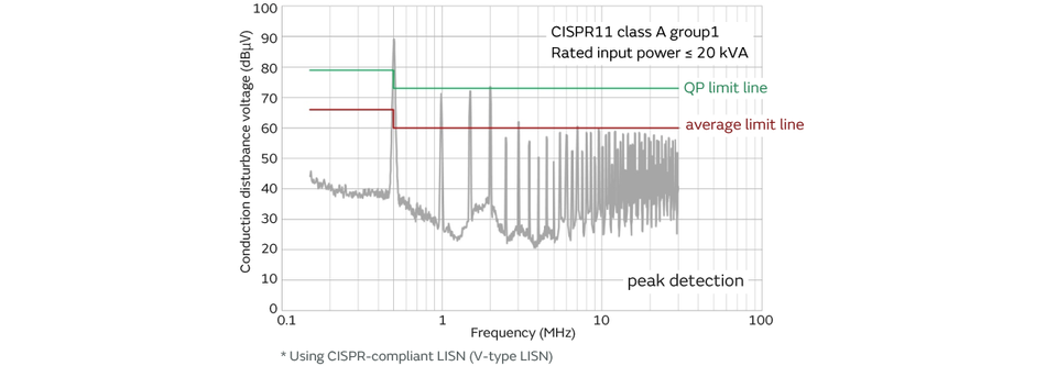
- A noise spectrum is generated at frequencies that are a multiple of the switching frequency of 500 kHz.
- Noise source: DC-DC converter (switching noise)
- Path: noise is conducted to the input DC power supply line (DC positive, negative)
Conducted noise mode separation (separated into differential/common mode)
Because we verified that there is a need to suppress the conducted noise (suppression is required to meet the noise specifications), we performed a mode separation of the conducted noise to verify the noise tendencies. The mode separation mentioned here is separated into differential mode voltage and common mode voltage. This mode separation is performed using a Delta-type LISN (Delta-type line impedance stabilization network).
*If we look at the CISPR noise specifications, the use of a V-type LISN is stipulated, and compliance with the noise specifications cannot be determined in the evaluation results with the Delta-type LISN. The robot noise specifications are being formulated, and it is thought that the V-type LISN will probably be used. In order to understand the noise tendencies, here we are using a Delta-type LISN instead of the V-type LISN used in the standard.
As a result of performing the mode separation, we can see that the differential mode noise is high in all frequency bands. Therefore, we need to suppress the noise with a filter that can control the differential mode.
*Because the differential mode noise is dominant in this case example, the conducted noise cannot be controlled even if a filter such as a common mode choke coil, which can control only the common mode, is used.
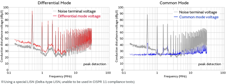
- All frequency bands are affected by the differential mode voltage.
- We can see that differential mode noise suppression is needed.
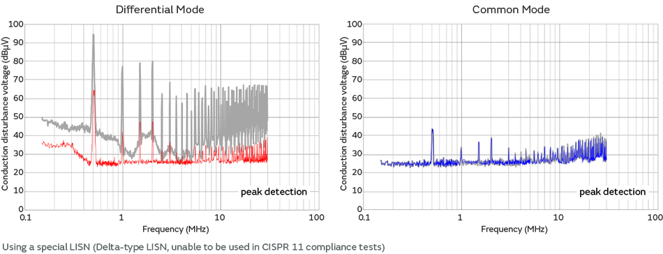
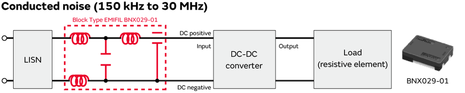
The differential mode was dominant in all frequency bands of the power supply circuit conducted noise in this case example. A Block Type EMIFIL (High-Current, High-Attenuation) BNX029-01 is used as the filter configuration that can control this differential mode voltage.
(Reason for selecting the BNX Series)
The LC π-type filter is a representative filter configuration that controls the differential mode voltage in the 150 kHz to 30 MHz frequency band. When configuring this LC π-type filter, one may consider configuring it with a 470 uF electrolytic capacitor and a 1 mH inductor, for example. On the other hand, components such as electrolytic capacitors are not desirable in robots and other power supplies from the perspective of conserving space, reducing the number of components, and high reliability. Therefore, we selected the BNX029-01 Block Type EMIFIL (High-Current, High-Attenuation) as a filter that can satisfy the requirements above.
By inserting the BNX into the DC line, we were able to significantly control the differential mode voltage in all frequency bands.
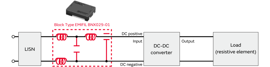
- The differential mode voltage can be significantly controlled in all frequency bands.
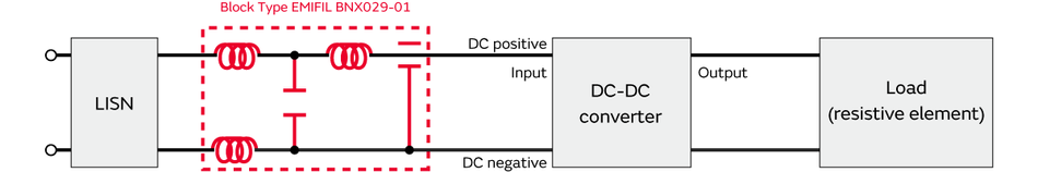
We measured the conducted noise before and after the noise suppression with a V-type LISN, which is expected to be used in the noise regulations.
By inserting the BNX into the DC line, we were able to satisfy the CISPR 11 noise tolerances in all frequency bands. Performing mode separation on the conducted noise and suppressing the mode that is causing the noise in a concentrated manner in this way enables effective noise suppression.
By using this kind of suppression method, you can select a filter configuration without backtracking in addition to being able to shorten the time spent on suppression. Moreover, because you can implement suppression based on data rather than uncertain information such as experience or intuition, this enables noise suppression with a minimum amount of effort regardless of the power supply circuit.

- Satisfying the noise tolerances by controlling the differential mode.
Summary of DC-DC converter noise suppression

Pseudo-robot emission suppression (radiation noise)
As the second case example of robot emission suppression, we introduce the case example of radiation noise suppression evaluated between 30 MHz and 1 GHz. In this part, we discuss two case examples concerning (1) brush motor noise and (2) brushless motor noise.
Case example of brush motor noise
Case example: Evaluation of radiation noise in an AGV driven by a DC motor with a built-in brush
As a case example of the radiation noise of a brush motor, we investigated radiation noise in an AGV (Automated Guided Vehicle) driven by a DC motor with a built-in brush.
In this investigation, we laid down magnetic tape in a circle on the floor of an anechoic chamber and had the AGV run in a circle on top of that magnetic tape to measure the noise.
The AGV is driven by a DC motor with a built-in brush.

- The AGV ran in a circle over the circular magnetic tape.
- The CISPR 11 measurement environment was referenced to evaluate the radiation noise in an equipment layout based on the expected actual use environment.
We investigated the radiation noise before noise suppression.
A noise spectrum was observed in a broad frequency band from 30 MHz to 1 GHz.
In addition, a noise spectrum exceeding the noise tolerances was observed in some sections.
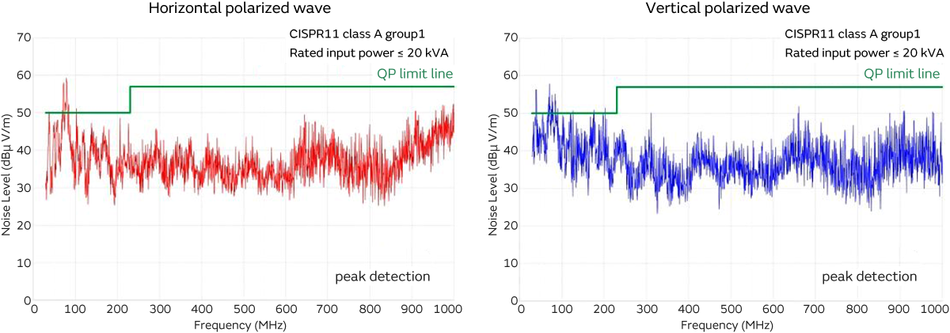
- Needle-shaped noise spectrum observed across a broad frequency band
Radiation antenna investigation (noise isolation)
We investigated the radiation noise generation mechanism in a manner similar to the commercial robot investigation.
The radiation antenna investigation is extracted and shown here.

- Noise source: brushed DC motor discharge noise
- Path: The motor discharge noise is conducted to the cable
- Radiation antenna: cable which connects the control board and the motor
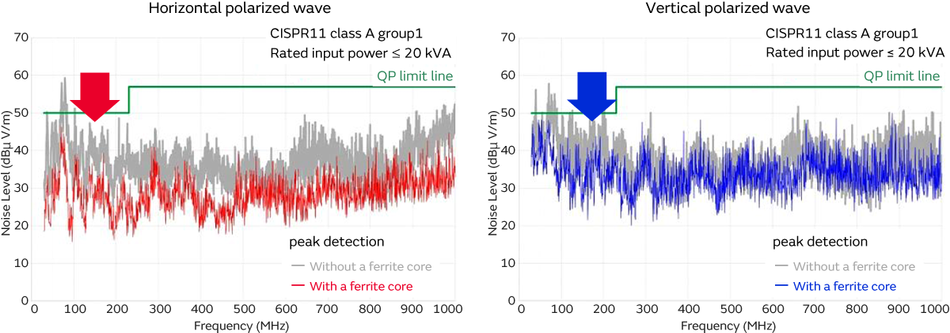
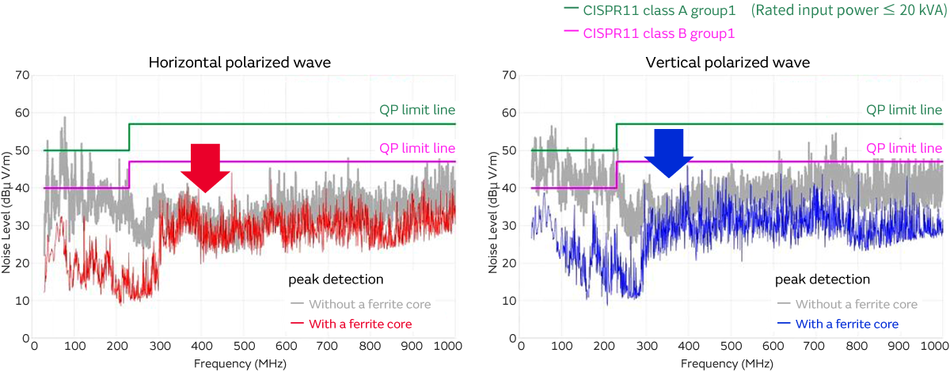
- The level of radiation noise decreases due to the ferrite core.
When one ferrite core was attached to the cable connecting the motor and the control board, the radiation noise spectrum decreased in all frequency bands. As a result, the noise source, conducting path, and radiation antenna can be considered as shown in (1) through (4) in the figure below.
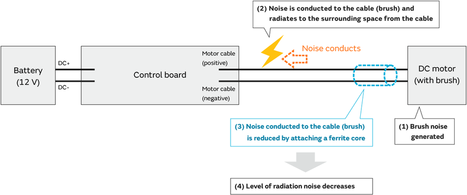
Brush noise is generated when the brushed motor runs. This brush noise is always generated due to the operating principle of the brushed motor. This brush noise is conducted to the cable shown in (2). Most of the cables used in robots are vinyl coated cables, and shielded cables are rarely used. In other words, when noise is conducted to vinyl coated cables, it is radiated into the surrounding space.
This section explains the radiation antenna investigation that was indicated earlier. When a ferrite core is attached to the cable connecting the motor and control board (cable shown in (2)), the brush noise generated by the motor is inhibited by the ferrite core, which makes it difficult for the noise to flow into the cable. (*Because the cable impedance increases with the ferrite core, it is difficult for the noise to conduct.)
Since it is difficult for the noise to conduct to the cable shown in (2), the noise radiating from the cable decreases.
In this case example, the noise source is the brush noise of the brushed motor, and the radiation antenna was the cable shown in (2).
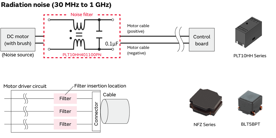
Brush noise suppression example
This section introduces a case example of suppressing brush noise with a filter.
This case example used a common mode choke coil (PLT10HH) and an X capacitor (0.1 uF).
We investigated the noise before and after the suppression with this filter configuration.
By inserting the filter, we are able to reduce the noise spectrum in all frequency bands.
In addition, we were also able to satisfy the noise tolerances and effectively control the radiation noise with a small number of components.

- Do not allow the noise generated by the motor (brush) to conduct to the cables.

- Radiation noise significantly decreases.
Summary of brushed motor radiation noise suppression
Common mode choke coil (PLT10HH401100PN)
Case example of brushless motor noise
To continue, we introduce (2) a case example of brushless motor noise.
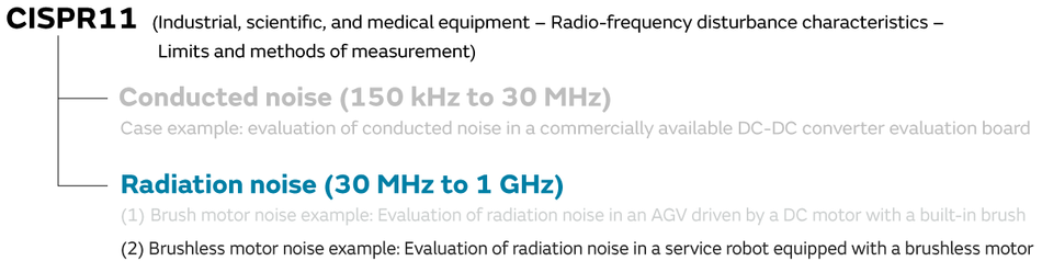
Case example: Evaluation of radiation noise in a service robot equipped with a brushless motor
As a case example of the radiation noise of a brushless motor, we introduce an example of radiation noise using a service robot. Furthermore, because AC power is sometimes supplied to service robots in a shared pole-mounted transformer or other public distribution network, the noise tolerances applied Class B.

These are the radiation noise evaluation results before the noise suppression.
It is believed that in many robots radiation noise is prone to becoming a problem in the 30 MHz to 100 MHz frequency band (200 MHz in this case example).
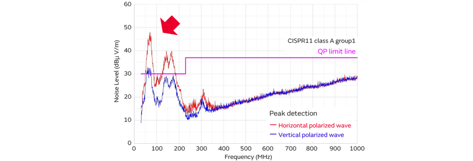
- Noise spectrum observed between 30 MHz and 200 MHz.
A brushless motor was adopted as the motor for the evaluation equipment.
A motor driver circuit is required to operate the brushless motor. Typically, the driver circuit of a brushless motor adopts a three-phase PWM control circuit.
This control circuit is composed of two switching elements for each phase (total of six), and each phase applies a continuous current to the motor by turning on and off at the right time.
This is not limited to robots, but switching noise is generated, because the motor driver circuit is composed of switching elements. When the switching noise is conducted to the cables, the noise from the cables radiates into the surrounding space, because the cables used in the robots are insulating layer cables with no shielding.
In addition, because noise is also conducted to the winding coils inside the motor, noise also radiates from the motor unit.
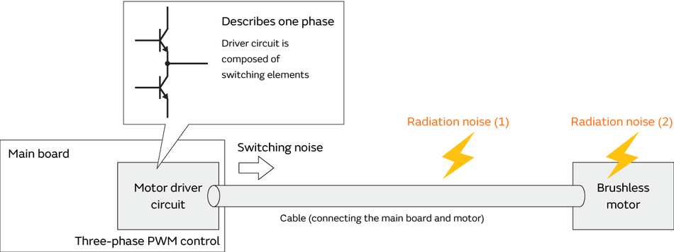
- Noise source: motor driver circuit switching (switching noise)
- Paths: Noise is conducted to the cable that connects the board and the motor
- Radiation antenna:
(1) Cable that connects the board and the motor
(2) Motor unit (winding coils inside the motor)
The switching noise generated by the motor driver circuit is conducted to and radiates from the cables and motor unit.
As a measure to suppress this noise, a noise filter is inserted close to the connector. A filter with insertion loss between 30 MHz and 200 MHz (up to 300 MHz) is selected for use here.
(Ex.) BLM31KN471SN1, NFZ Series, BLT5BPT, etc.
The rated current of the filter to be inserted in each line of the motor should be noted here. If the current during normal motor operation is 1 (A), it would be desirable to select a component with three to five times the rated current.
(Reason)
If the motor locks for some reason while running, an instantaneous spike current may flow. A component that will not malfunction even if such an instantaneous current flows must be selected.
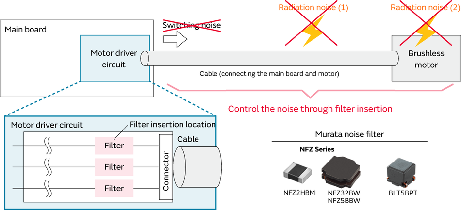
- Do not allow the ( switching ) noise generated by the driver circuit to be conducted to the cables.
NFZ Series (NFZ2HBM/NFZ32BW/NFZ5BBW)
Noise filter-based suppression
We investigated the radiation noise before and after the filter insertion. A NFZ2HBM4R4SN10 filter was used.
A noise margin of 5 dB or more with respect to the standard tolerance was ensured by inserting the filter. In this way, the radiation noise can be effectively controlled by using a filter in the noise-conducting path.

Noise filter (NFZ2HBM4R4SN10)
- Radiation noise can be effectively controlled by inserting a filter.
Summary
We introduced examples of conducted noise and radiation noise suppression as examples of robot emission suppression. Regarding radiation noise, we introduce examples of brushed and brushless motors. In either case, we were able to investigate the noise generation source, conducting path, and radiation locations to suppress the noise by setting the appropriate noise filter in the conducting path.
7-1. Robot emission suppression proposal CISPR11
Noise suppression products proposed by Murata
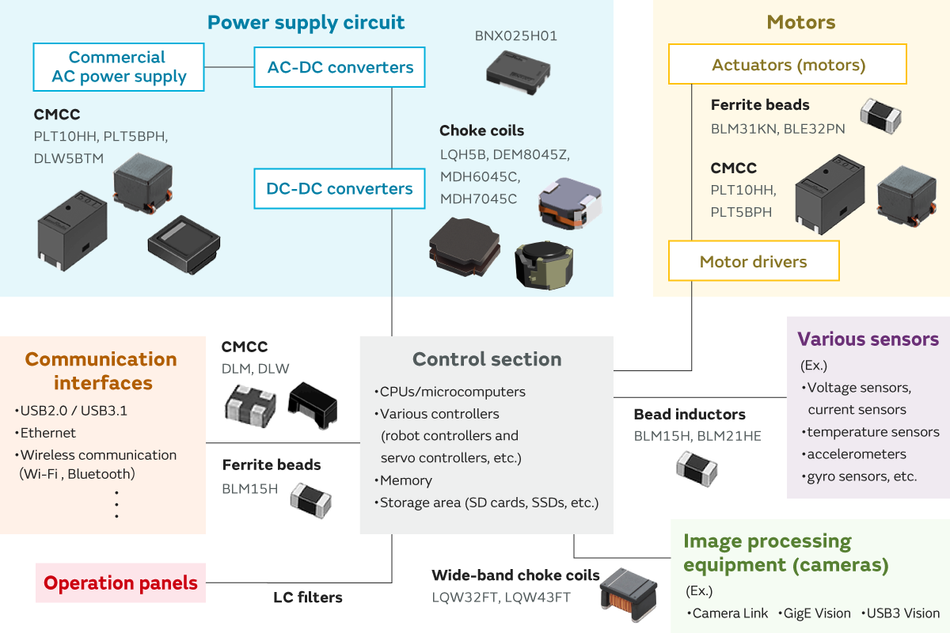
CMCC (PLT10HH/PLT5BPH/DLW5BTM)
Choke coils (LQH5B/DEM8045Z/MDH6045C/MDH7045C)
Ferrite beads (BLM31KN/BLE32PN)
Ferrite beads (BLM15H)