An A-Z Guide to CNC Machining Technology
CNC machining where precision meets innovation.
CNC machining where precision meets innovation. In this blog, we'll explore the macroscopic number of technical terms that shape the landscape of CNC machining and dismantle them - to gain a true understanding of their meaning.
Arbor – a cylindrical shaft or spindle used to securely hold a cutting tool or workpiece in place during machining operations.
Axis – The direction along which a cutting tool or workpiece can move under the control of the CNC system. The most common axes are X (left to right or vice versa), Y (front to back or vice versa), and Z (typically up and down).
Ball Nose End Mill – a milling cutter with a rounded tip or “nose” that resembles a ball. Allows the end mill to create contoured surfaces or complex three-dimensional shapes with smooth finishes.

CAM (Computer-Aided Manufacturing) – software that converts 3D CAD designs into CNC machine instructions.
Datum – a fixed reference point or surface. The datum serves as the origin point from which all measurements and movements of the cutting tool or workpiece are referenced.
EDM (Electrical Discharge Machining) – a non-traditional machining process. Material is removed from a workpiece through electrical discharges between an electrode and the workpiece submerged in dielectric fluid.
End Mill – a type of cutting tool used to remove material from a workpiece.
Feed Rate – the speed at which the cutting tool moves along the workpiece during a machining operation. Typically expressed in units of distance per unit of time, such as millimetres per minute (mm/min).
G-Code – a programming language used to control the movement and operation of CNC machines. It consists of a series of alphanumeric codes that represent specific commands, movements, tool changes, and other instructions necessary to produce a desired part or component.
Hard Turning – a machining process performed on CNC machines that is specifically designed for the high-precision machining of hardened materials. It is an alternative to traditional grinding processes or finishing hardened workpieces.
High-Speed Machining (HSM) – is a CNC machining technique that involves using higher cutter speed and feed rates to achieve faster material removal rates while maintaining or improving surface finish and dimensional accuracy. HSM is characterised by its ability to remove material at significantly higher speed than conventional machining processes.
Indexable Inserts – also known as indexable cutting inserts or simply inserts, are replaceable cutting tools that can be quickly and easily changed to accommodate different materials and applications. These inserts are typically made of carbide, ceramic, cermet, or other hard materials and are designed to be mounted onto cutting tool bodies, such as end mills, milling cutters, turning tools, and drills.
Interpolation – the process of calculating intermediate points between two known points to create a smooth and continuous path for the cutting tool to follow. Interpolation is essential for generating complex toolpaths that involve curves, arcs, and other non-linear movements. Ther are several types of interpolation – linear, circular, helical and spline.

Jig – a device used to hold and locate a workpiece or a tool in the correct position relative to the cutting tool and the machine. Commonly used in CNC to ensure accuracy, repeatability, and efficiency.
Jog – “jogging” refers to the manual movement of the CNC machine’s tool or workpiece along a particular axis or direction. It is controlled and incremental movement used for various purposes, such as setting up the machine, positioning the tool or workpiece, checking clearances, or making small adjustments during the machining process.
Kerf – the width of material that is removed by a cutting tool during a machining operation, such as milling, routing, or laser cutting.
Keyway – refers to a specific type of slot or groove that is cut into a shaft or hub of a mechanical component to accommodate a key.
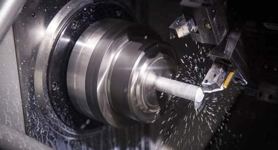
Lathe – also known as a “turning machine” is a machine that rotates the workpiece while a cutting tool is brought into contact with it to remove material and create the desired shape. Lathes offer versatility, precision, and efficiency in producing a wide range of cylindrical or conical components and parts.
M-Code – are special commands used to control various auxiliary functions to the machine tool or to activate specific machine operations. They are part of the CNC programming language and are typically used alongside g-codes, which control the movement and positioning of the machine’s cutting tool. Som examples of M code are M03 – for spindle clockwise rotation, M08 for coolant on, or M06 for tool change.
Machining Centre – a type of CNC machine that combines several machining processes into one machine. A highly versatile and automated machine tool capable of performing a wide rang of machining operations on a workpiece. Key features include multi-axis capability, automatic tool changer (ATC), spindle, control system, workpiece handling, and integrated coolant systems.
Nudge – a small incremental movement of the axes of a CNC machine to fine-tune tool positioning. Typically done using the machine’s control panel, pendant, or jog handle.
Offset – the difference between the programmed position of the cutting tool and its actual position relative to the workpiece. Commonly used to compensate for tool dimensions, workpiece dimensions, or machine inaccuracies.
Overcut – the intentional extension of a cutting tool’s path beyond the programmed endpoint of a machining operation.

Paperless Manufacturing – the practice of digitising and automating the entire manufacturing process, eliminating the need for paper-based documentation, drawings, and instructions.
Pocketing – a machining operation used to remove material from an enclosed area on a workpiece.
Quick Change Chuck – a type of workpiece holding device that allows for raid and tool-free mounting and removal of workpieces. Designed to minimise downtime associated with tool changes.
Quill – a feature found in certain types of milling machines, particularly manual or semi-automatic. The vertical component on a milling machine that houses the spindle and cutting tool.
Rapid Traverse – refers to high-speed movement of the machine’s cutting tool or workpiece. A rapid linear movement along one or more axes of the CNC machine, typically performed at the maximum travel speed.
Roughing – the initial phase of material removal from a workpiece during the machining process to achieve the desired shape.
Spindle – refers to the rotating component of the machine tool responsible for holding and driving the cutting tool. The spindle rotates at high speed to perform various machining operations such as milling, drilling, boring, or grinding.
Spindle Speed – the rotational speed of the spindle. A critical parameter in CNC machining as it directly affects cutting performance, tool life, surface finish, and the overall efficiency of the machining process. Measured in revolutions per minute (RPM).
Toolpath – the precise path that a cutting tool follows during a machining operation. There are a variety of toolpaths including, contouring, pocketing, profiling, drilling, 3D machining, and more.
Undercut – a recessed or indented feature in a workpiece that prevents the cutting tool from reaching certain areas or angles during machining.
Vernier Caliper – a precision measuring instrument used for dimensional inspection of machined parts.
Virtual Manufacturing – the use of computer simulations and modelling techniques to analyse, optimise, and validate manufacturing processes before physical implementation. In CNC this can refer to using process simulation, collision detection, toolpath optimisation, fixture and design validation, process validation and verification, and training and skill development.
Work Coordinate System – or WCS, refers to a set of reference axes and coordinates used to define the position and orientation of the workpiece or part relative to the CNC machine’s cutting tool.
Workholding – the process of securing and clamping the workpiece in place on the CNC machine’s table or fixture during machining operations.
X-Axis – horizontal movement (from left to right or vice versa) of the cutting tool along the length of the workpiece. Usually, oriented perpendicular to the Y-axis and parallel to the machine’s bed or table.
Y-Axis – horizontal movement (from front to back or vice versa) of the cutting tool along the length of the workpiece. Usually, oriented perpendicular to the X-axis and parallel to the machine’s bed or table.
Z-Axis – vertical movement (up and down or vice versa) of the cutting tool. Commonly the z-axis is oriented perpendicular to both the x-axis and y-axis.
Zero Point – the reference point from which all coordinates and movements of the cutting tool and workpiece are measured. It serves as the origin for the WCS work coordinate system and is used to define the starting point for CNC programming and machine operations.
These are just some of the terms you may hear referred to when discussing CNC machining. To discover more about CNC machining, visit our webiste.
