Capacitor Polarity: Ensuring Proper Orientation for Optimal Performance
This guide explores the crucial factors in capacitor polarity, its mathematical analysis, identification, and advanced practices for improved circuit performance.

01 May, 2024. 11 minutes read
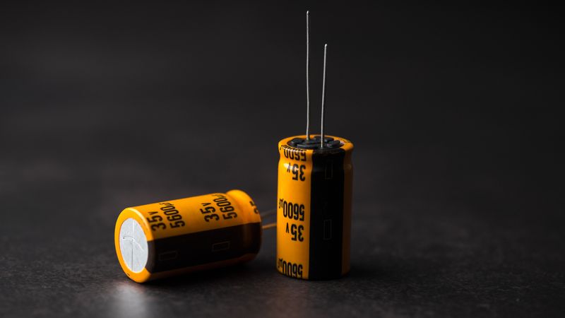
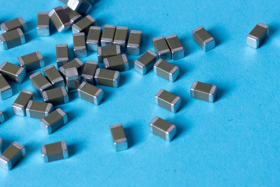
Isolated capacitor, used in electronic devices
No time now? Save for later.
We only use your email to send this link. Privacy Policy.
Introduction
Capacitors are fundamental passive components that store electrical energy in an electrostatic field. They fulfil a critical role in electronic circuits by filtering signals, smoothing power supply fluctuations, and providing temporary energy storage. However, unlike their resistor counterparts, capacitors possess a vital characteristic known as capacitor polarity.
Capacitor polarity is a critical aspect of capacitor design and operation, determining the direction of electric charge flow and proper functioning within electrical circuits. Understanding capacitor polarity and ensuring proper installation is essential for optimal performance and preventing catastrophic failure within a circuit. Failure to observe correct polarity during installation can lead to component damage, circuit malfunction, and potential safety hazards. Let’s get into the physical principles of capacitor polarity.
Physical Principles of Capacitor Polarity
Capacitor polarity arises from the fundamental concept of electric fields. A capacitor comprises two conductive plates separated by an insulating dielectric material. When a voltage is applied, an electric field forms within the dielectric, causing positive and negative charges to accumulate on the respective plates. Positive charges accumulate on one plate (typically denoted as the anode), while negative charges accumulate on the other (the cathode). This creates an electric potential difference across the capacitor, allowing it to store and release energy within circuits.
However, the key to capacitor polarity lies in the type of dielectric material used. Non-polar capacitors utilize symmetrical dielectrics like films or ceramics. These materials respond equally to an electric field regardless of its direction. In contrast, polarized capacitors rely on an electrolytic material, often formed by an oxide layer on one of the plates.
Permittivity, denoted by the symbol ε (epsilon), represents the material's ability to store and concentrate electric fields. [1] Higher permittivity materials allow for a stronger electric field within the same voltage, leading to a greater concentration of charges on the plates and, consequently, a higher capacitance.
The orientation of the electric field dictates polarity. The positive plate accumulates positive charges, while the negative plate accumulates negative charges, creating an electric potential difference across the capacitor for energy storage and release in circuits.
Let’s get into the details, construction, and features of non-polar vs. polarized capacitors.
Capacitor Fundamentals: The Basics of Polarity
Capacitor polarity refers to the specific orientation of a capacitor's positive and negative terminals within an electrical circuit, determined by its internal structure of two conductive plates separated by a dielectric material.
Capacitors are classified as polarized or non-polarized based on their polarity requirements:
| Feature | Polarized Capacitors | Non-Polarized Capacitors |
| Dielectric Material | Electrolytic (asymmetric behavior) | Film (ceramic, plastic) (symmetric) |
| Polarity | Requires specific voltage direction (+ to anode) | No specific voltage direction |
| Capacitance | Generally higher capacitance for size | Generally lower capacitance for size |
| Applications | Power supply filtering, smoothing | Signal coupling, filtering (AC circuits) |
| Examples | Tantalum capacitors, Aluminum electrolytic capacitors | Ceramic capacitors, Film capacitors (polyester, polypropylene) |
Polarized capacitors, like electrolytic and tantalum types, have a thin oxide layer on the anode plate acting as the dielectric, allowing high capacitance in a compact size. Reverse polarity can break down this oxide layer, leading to failure and potential circuit damage.
Non-polarized capacitors, such as ceramic, plastic film, and mica types, have a uniformly distributed dielectric between the plates. This enables symmetrical charge distribution and polarity-independent operation.
Polarized Capacitors: Electrolytic and Tantalum Capacitors
The defining characteristic of a polarized capacitor is its asymmetrical behavior. Unlike a film or ceramic capacitor, a polarized capacitor relies on a special dielectric layer formed on one of its plates. This layer, typically an oxide layer in electrolytic capacitors and a pentoxide layer in tantalum capacitors, is crucial for maximizing capacitance. However, it's also susceptible to damage if the voltage is applied in the wrong direction.
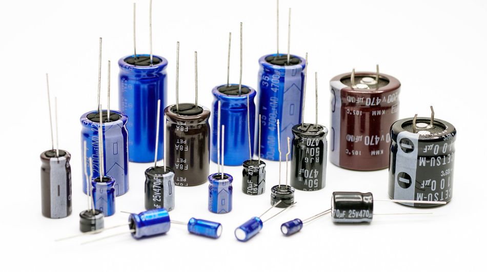
Electrolytic Capacitors
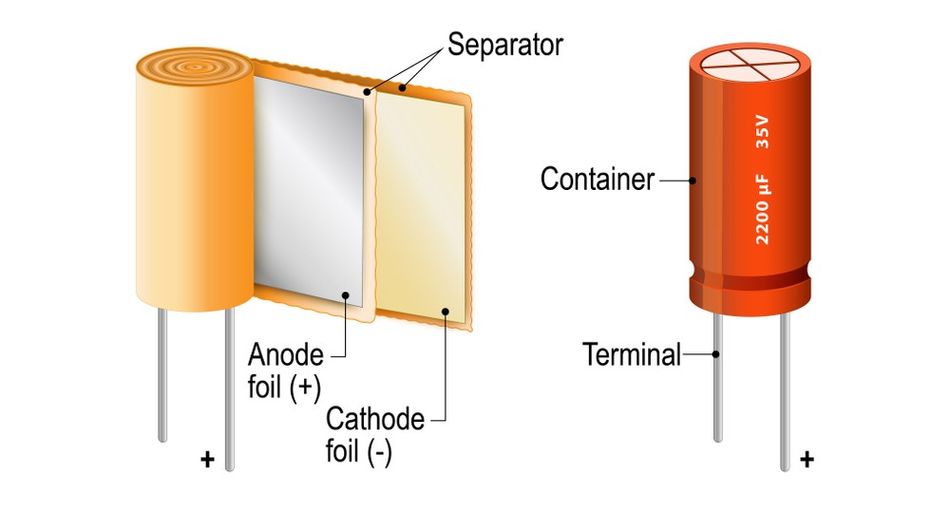
Electrolytic capacitors utilize an electrolytic solution as the main electrolyte and an aluminium foil as the base anode plate. The formation of an oxide layer on the anode during manufacturing creates the essential asymmetric dielectric.
Pros: Electrolytic capacitors are renowned for their high capacitance-to-volume ratio, making them ideal for applications requiring substantial energy storage in a limited space. They are also generally cost-effective.
Cons: Electrolytic capacitors have higher leakage current compared to non-polar types of capacitors. They also exhibit higher ESR (Equivalent Series Resistance), impacting circuit performance at high frequencies. Additionally, they have a shorter lifespan and are more susceptible to temperature variations.
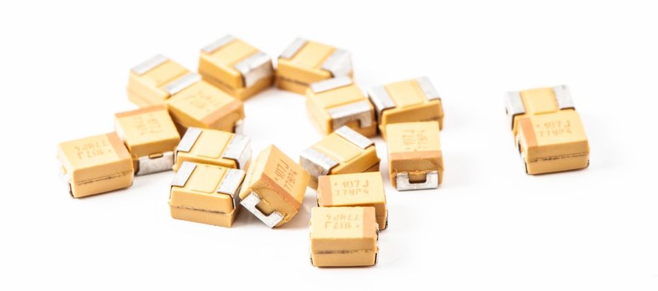
Tantalum Capacitors
Tantalum capacitors employ a tantalum metal base plate and a tantalum pentoxide layer as the dielectric. This combination offers a very thin yet effective insulating layer, leading to a higher capacitance-to-volume ratio than electrolytic capacitors. [2]
Pros: Tantalum capacitors boast lower leakage current and ESR than electrolytics, making them suitable for high-frequency applications. They are generally more compact and offer longer lifespans under moderate operating temperatures.
Cons: Tantalum capacitors are more expensive than electrolytics. They are also more susceptible to catastrophic failure if the voltage is reversed or exceeded. Additionally, their capacitance can degrade significantly at high temperatures.
The selection between electrolytic and tantalum capacitors depends on your specific circuit requirements. For high capacitance needs and cost-effectiveness, prioritize electrolytic capacitors. For applications demanding low leakage current, low ESR, and a smaller footprint, tantalum capacitors are the preferred choice. However, be mindful of the higher cost and potential for catastrophic failure under improper conditions.
Non-polarized Capacitors: Ceramic and Film Capacitors
The defining characteristic of a non-polarized capacitor lies in its symmetrical construction. The dielectric material, the insulating layer separating the conductive plates, responds equally to an electric field regardless of its direction. This allows for placement in a circuit without heeding polarity, simplifies assembly, and reduces the risk of errors. [3]
Ceramic Capacitors
Ceramic capacitors utilize a ceramic material, such as barium titanate, as the dielectric. This allows for a compact design, making them ideal for limited-space applications.
Pros: Ceramic capacitors offer high capacitance values in small packages. They also exhibit low ESR (Equivalent Series Resistance), making them suitable for high-frequency applications. Additionally, they generally have a long lifespan and can withstand high operating temperatures.
Cons: The capacitance of ceramic capacitors can vary significantly with temperature and applied voltage. They also tend to have a higher leakage current compared to some film capacitors.
Film Capacitors
Film capacitors utilize a thin plastic film, such as polyester or polypropylene, as the dielectric material. The film is sandwiched between two metal plates, typically aluminium foil.
Pros: Film capacitors offer excellent capacitance stability over a wide range of temperatures and voltages. They also have a very low leakage current, making them ideal for applications requiring high signal integrity.
Cons: Film capacitors generally have lower capacitance values compared to ceramic capacitors of similar size. Additionally, their larger footprint can be a limitation in space-constrained designs.
The selection between ceramic and film capacitors depends on the specific needs of the circuit. For high-frequency applications requiring low ESR and minimal capacitance variation, prioritize ceramic capacitors. Film capacitors are preferred for applications demanding exceptional capacitance stability, low leakage current, and precise signal handling. However, keep in mind their larger size and potentially lower capacitance values.
Recommended Reading: Types of SMD Components: A Comprehensive Guide
Mathematical Foundations of Capacitor Polarity
Capacitor polarity critically influences its electrical behavior, encapsulated by key equations. The fundamental relationship for capacitors is expressed as:
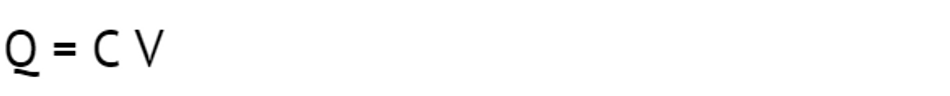
where Q represents the charge stored, C is the capacitance, and V is the voltage across the capacitor. This equation underscores the impact of voltage polarity on the charge accumulation. [4]
The current in a circuit with a capacitor, known as Capacitive Current is defined by:
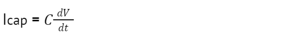
where Icap is the capacitive current, C is the capacitance, dV is the fractional voltage, and dt represents fractional time.
During the charging phase of a polarized capacitor, the relationship I = C ✕ dV/dt holds true. The current flowing into the capacitor is proportional to the rate of voltage change across its terminals. However, it's essential to remember the importance of capacitor polarity.
Example: Consider a DC circuit where a polarized capacitor (like a tantalum capacitor) is correctly connected to a battery, with the positive terminal of the battery connected to the anode (positive terminal) of the capacitor. In this scenario, the initial current will be high as the voltage difference is maximal. As the capacitor charges, the voltage across it increases, and according to the equation, the current will decrease. This exemplifies I = C ✕ dV/dt in real-time.
These mathematical principles are essential for circuit design, enabling engineers to predict capacitor behavior under various voltage scenarios and emphasizing the necessity of maintaining correct polarity to avoid damaging reverse charging.
Recommended Reading: How to Discharge a Capacitor: Comprehensive Guide
Identifying Capacitor Polarity: Markings and Symbols
Capacitors are marked with symbols to indicate polarity, crucial for ensuring correct installation. Common markings include:
Plus and Minus Signs (+/-): The most common method utilizes positive (+) and negative (-) signs printed directly on the capacitor body. The positive sign (+) near the terminal typically identifies the lead or terminal connected to the anode, while a stripe or arrow on the side represents the negative terminal.
Lead Length: Sometimes, the lead connected to the negative terminal may be shorter than the positive lead. This subtle difference can serve as a visual indicator of polarity. In through-hole capacitors, the longer lead indicates the positive terminal.
Colored Band: Surface-mount capacitors often have a colored band on the side corresponding to the negative terminal. Consult the capacitor datasheet for the manufacturer's specific color coding scheme.
Indented Band or Chamfered Edge: For certain electrolytic capacitors, an indented band or a chamfered (angled) edge on the can may indicate the positive terminal.
Circuit Board Notations: Sometimes, the negative terminal is marked directly on the circuit board instead of the capacitor.
These markings are vital for preventing the reverse installation of capacitors, which can cause device failure or damage. Using a multimeter can help a lot in determining the polarity or terminals of a capacitor.
The Consequences of Incorrect Capacitor Orientation
Incorrectly connecting a capacitor, particularly polarized types like electrolytics, can lead to catastrophic outcomes.
Here’s what typically happens:
Dielectric Breakdown: The most critical consequence is the breakdown of the dielectric material, typically a thin oxide layer formed on the anode. This layer plays a crucial role in maximizing capacitance and preventing leakage current. When the voltage is reversed, the electric field stresses the oxide layer beyond its limits, causing it to degrade, known as dielectric breakdown.
Heat Generation: This breakdown drastically increases leakage current, allowing unwanted current flow even when the capacitor isn't charging or discharging. This surge in current translates to heat generation within the capacitor.
Physical Damage: Excessive heat can cause the capacitor's internal components to expand and deform. In severe cases, the capacitor may swell, leak, or even explode (physical damage). A vented or exploded capacitor can damage surrounding electronic components or SMD devices, posing a safety hazard.
Circuit Failure: The damaged capacitor can disrupt the circuit, potentially harming other components and causing overall circuit failure.
Even if a capacitor with reversed polarity doesn't experience immediate failure, the ongoing leakage current can gradually degrade its performance over time. This can lead to premature component failure and potential circuit malfunctions. Following proper polarity during capacitor installation can prevent these consequences and ensure the safe, reliable, and long-term functionality of your electronic circuits.
Advanced Topics in Capacitor Polarity
Capacitor polarity influences long-term performance through factors like equivalent series resistance (ESR) and aging effects. ESR, which measures the internal resistance that opposes AC current, can affect capacitor efficiency and heat generation, impacting power regulation circuits. [5]
Aging effects, exacerbated by incorrect polarity, cause capacitors to lose capacitance and increase leakage current over time, altering circuit behavior and leading to failure. These effects are accelerated by high temperatures and reverse polarity stress.
Capacitor datasheets specify a maximum voltage rating for safe operation. However, for polarized capacitors, it's often recommended to operate them at a voltage lower than the absolute maximum, a practice known as voltage derating.
Some types of tantalum capacitors exhibit self-healing properties. When a microscopic breakdown occurs in the oxide layer due to a voltage spike or surge current, a localized high-temperature zone forms. This heat vaporizes the surrounding electrolytic material, isolating the breakdown point and preventing further damage. However, these self-healing events can reduce the capacitor’s overall capacitance over time.
Methods to manage these issues include:
ESR Measurement: Using meters and impedance analyzers to monitor ESR levels.
Thermal Management: Implementing heat sinks and ensuring proper ventilation.
Circuit Design: Incorporating overvoltage protection to prevent damage from reverse polarity.
By incorporating these management techniques, users can proactively address the potential issues associated with capacitor polarity in advanced applications. Remember, prevention is key to ensuring the longevity and reliability of polarized capacitors within your electronic designs.
Best Practices for Ensuring Proper Capacitor Polarity
Proper capacitor polarity is essential for circuit functionality and longevity. To ensure correct orientation:
Before Installation:
Check the capacitor's polarity markings against the circuit board's indicators.
Align the positive terminal with the circuit board's positive pad, and the negative with the negative pad.
For through-hole capacitors, adjust the leads to fit the board layout without stressing the capacitor.
Installation Steps:
Identify the capacitor's terminals.
Match the terminals with the board's polarity pads.
Solder carefully to avoid heat damage.
Selection Guidelines:
Use capacitors with voltage ratings above the circuit's maximum voltage.
Select capacitors with suitable temperature ratings for the operating environment.
In circuits with variable polarity, use non-polarized capacitors when feasible.
Following these practices ensures capacitors are installed correctly and operate reliably.
Recommended Reading: Supercapacitor FAQ
Conclusion
We've explored the critical aspects of capacitor polarity, from basic concepts and identification markers to the consequences of incorrect polarity and advanced considerations. Understanding and respecting capacitor polarity is essential for the safe and effective design and operation of electronic circuits. Looking ahead, advancements in capacitor technology are likely to further enhance their efficiency and functionality, playing a pivotal role in the evolution of electrical engineering.
Frequently Asked Questions
Q. What is capacitor polarity?
A. Capacitor polarity refers to the correct alignment of a capacitor's positive and negative terminals according to the circuit design.
Q. Why is it important to observe capacitor polarity?
A. Incorrect polarity can lead to capacitor failure, circuit damage, and safety hazards.
Q. How can I identify the polarity of a capacitor?
A. Look for markings, such as a stripe for the negative terminal or a plus sign for the positive terminal. A multimeter can also help a lot in this process.
Q. What happens if a capacitor is installed backwards?
A. It may lead to the breakdown of the dielectric material, overheating, and potential explosion.
Q. Can non-polarized capacitors be used in any direction?
A. Yes, non-polarized capacitors do not have a polarity and can be installed in any direction.
Q. What are some tips for ensuring correct capacitor polarity during installation?
A. Always check the capacitor’s markings and the circuit board indicators before installation.
Q. What advancements in capacitor technology can we expect in the future?
A. Future advancements may include higher capacitance values, improved temperature stability, and enhanced durability.
References
[1] BYJU’S. Permittivity and Permeability [Cited 2024 April 26] Available at: Link
[2] eepower. Tantalum Capacitor [Cited 2024 April 26] Available at: Link
[3] Electrical Technology. Capacitor & Types Of Capacitors | Fixed, Variable, Polar & Non-Polar [Cited 2024 April 26] Available at: Link
[4] rowsum. Do Capacitors Have Polarity? Your Comprehensive Guide to Understanding [Cited 2024 April 26] Available at: Link
[5] nextpcb. Capacitor Polarity: What You Need to Know [Cited 2024 April 26] Available at: Link
in this article
1. Introduction2. Physical Principles of Capacitor Polarity3. Capacitor Fundamentals: The Basics of Polarity4. Polarized Capacitors: Electrolytic and Tantalum Capacitors5. Non-polarized Capacitors: Ceramic and Film Capacitors6. Mathematical Foundations of Capacitor Polarity7. Identifying Capacitor Polarity: Markings and Symbols8. Advanced Topics in Capacitor Polarity9. Best Practices for Ensuring Proper Capacitor Polarity10. Conclusion11. Frequently Asked Questions12. ReferencesNo time now? Save for later.
We only use your email to send this link. Privacy Policy.