Keeping it cool while on track
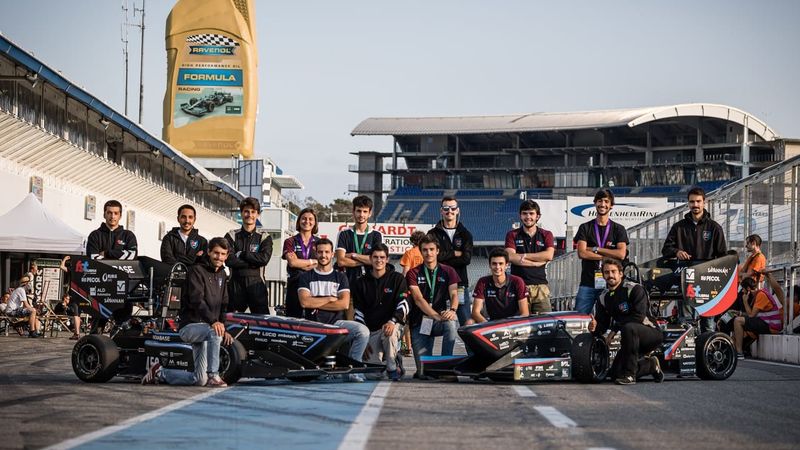
This year, Murata is sponsoring the Formula Student Team from the Instituto Superior Técnico, University of Lisbon, with a mixture of funding and electronic components.

Formula Student Team from the Instituto Superior Técnico, University of Lisbon.
Since 2001, the FST Lisboa team has been designing, building and testing formula type cars to compete internationally in the Formula Student competitions. During this time, they developed nine prototypes, of which three were combustion and the remaining electric.
The Formula Student competition challenges teams of university students from around the world to conceive, design, fabricate, develop and compete with small, single-seater race cars. In the electric vehicle (EV) class, it is critical to continuously monitor the battery temperature and keep it cool, especially during the endurance test. So much so, the competition rules stipulate that the team must monitor at least 30% of the Li-ion cells within the battery, which must not exceed 60°C. If the battery temperature hits 60°C, the team is disqualified instantly.
The big test for cooling
The endurance test is 20km and lasts for around 30 minutes, depending on the car’s performance. The race officials locate an independent cell temperature monitoring device on the rearmost part of the battery where, in theory, the cells are hotter. As the cells age, their body swells, eventually narrowing the spaces between each cell to such an extent that cells on the rear side of the battery become very challenging to cool.
“In previous competitions, air from outside was fed through to the inside of the battery for cooling the body of the cells,” says Miguel Lourenço, Electrical Systems Chief Engineer, FST Lisboa. “During the endurance test, especially in hot weather, we have reached very close to that temperature limit. Of course, every year, we try to improve the battery’s performance in the endurance test and, for optimal performance, we aim to keep the temperature at around 40°C.”
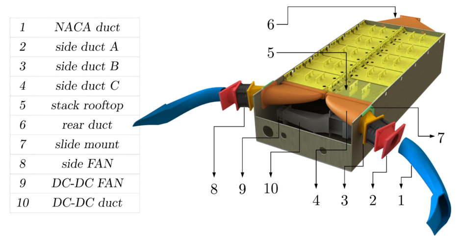
For this season’s car, the cooling system is significantly different, with some minor similarities. Based on various thermal studies, the team decided to cool the tabs on the pouch cells instead of cooling the entire body of the cell. Inlets on either side of the car were designed to scoop the air inside the battery. In addition, variable speed fans were incorporated into the air ducts - each controlled by the battery management system (BMS). There is also a fan located on the rear side of the battery to suck the warm air out, see Figure 1.
Battery management system
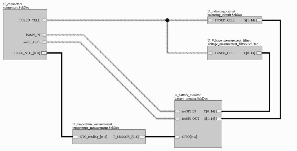
For the BMS, the Murata sensors are soldered next to the tabs of the individual cell to be measured and placed on top of it using thermal glue to enhance thermal conductivity. For temperature acquisition, a specialized Printed Circuit Board (PCB) is located in each segment of the battery, which is responsible for acquiring eight different temperatures. The circuitry used for this function is a simple voltage divider and a multicell accumulator stack monitoring device that communicates the measured temperature values via the SPI (Serial Peripheral Interface) communication protocol to the main module of the BMS, see Figure 2.
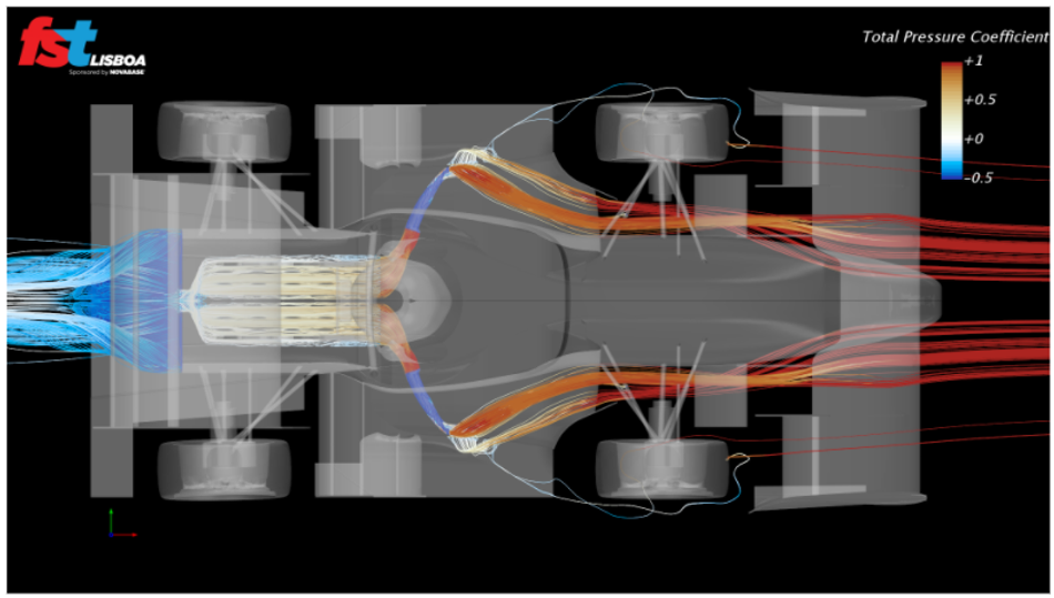
The battery monitor used in each battery segment has eight General Purpose Input/Output (GPIO) pins, all of which are used for temperature acquisition. One sensor is used to acquire the temperature of the cells’ passive balancing channels, and the other seven are used to measure cell temperature. This enabled the team to monitor the temperature of around 60% of the battery cells. Furthermore, this high level of cell monitoring allowed the team to better understand the accuracy of cooling simulations, see Figure 3. It also implemented redundancy; if one sensor fails, for example, the system is still monitoring above the mandated 30% rule.
The cooling fans are controlled by taking into account the highest cell temperature on each side of the battery, and a proportional controller is used to drive the fan from the respective side using the Pulse Width Modulation (PWM) technique.
“With these fans, we are able to individually control the amount of air that passes through both sides of the battery,” explains Lourenço. “Instead of relying on natural convection cooling, which was resulting in hot patches towards the rear of the battery, we were able to maintain the same cell temperature across the whole pack.”
Managing critical errors and battery health
Visual access to the measured AMS data, including the temperature, by connecting a laptop to the car is also stipulated within the rules. The is achieved using a dedicated device that converts CAN frame to serial, and when plugged into a laptop, the team can visualize all of the data.
However, if a temperature error should occur, the team needs to switch off the car within 1s, as stated by the rules. Using the CAN bus, with a speed of 1 Mbit/s, the BMS status is communicated from the decentralized BMSs to a dedicated PCB responsible for driving the status indicator light. Any failure in transmitting this information, being either loss of communication or data corruption, is handled, and the LED light illuminates to indicate that it is in a safe state.
“We did not look into the state of health (SOH) estimation of the battery, since it is a complex subject for the value that it adds to the car’s overall performance,” adds Lourenço. “Instead, we used passive cell balancing, where we discharge the battery from time to time using a pulse discharge technique, and the cell capacity is measured to determine the health of the pack.”
Conclusion
For this season, Murata’s involvement in providing automation-grade temperature sensors and other components for the powertrain has been a critical element of the development process. The team chose Murata automotive-grade sensors because of their low tolerance, which meant that they did not need to implement software to correct any measurement errors. This allowed them to go closer to the 60°C temperature limit and gave them the confidence that they needed for the endurance test. In addition, the insulated lead design allowed the team to place the sensor directly on top of the cell pad using thermal glue to enhance thermal conductivity, with flexibility and without the risk of a short circuit.
“This year was quite challenging in terms of communication within the team,” concludes Lourenço. “Motivation also played a major role as some members were not able to work as much as they might have wanted, for example, due to travel restrictions. In the end, and seeing the final result, it was well worth the sacrifice made over these two long years! Thank you Murata for all of your support.”
About the sponsor: Murata
Murata is a global solution provider and the market leader in the design, manufacture, and supply of advanced, leading-edge electronic components, and multi-functional modules. Murata contributes to the advancement of society and the electronics industry, in close cooperation with its customers and other stakeholders. Their European HQ is based in the Netherlands.

If you have any questions based on this article that you would like to discuss with an expert at Murata, don't hesitate to reach out. There's an entire team ready to support you with your question.


