Loper
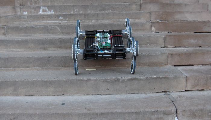
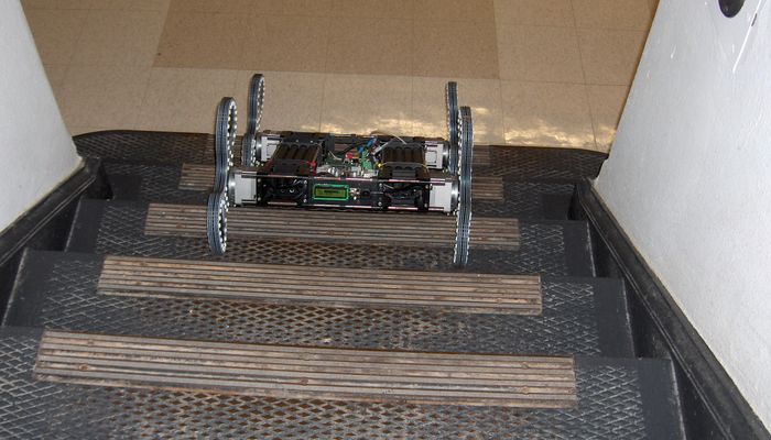
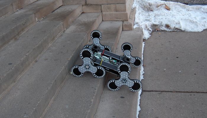
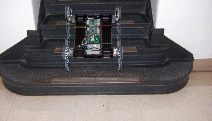
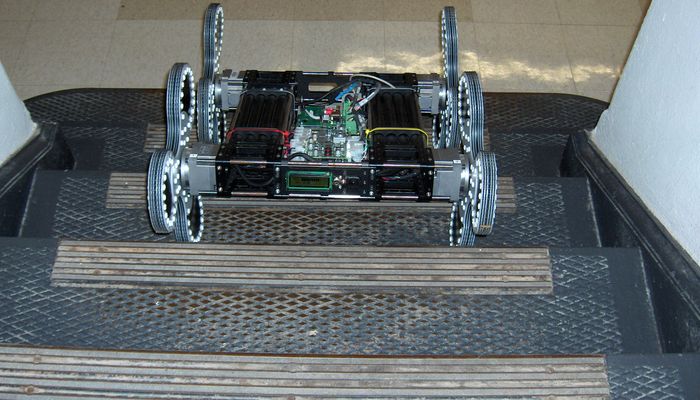
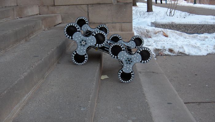
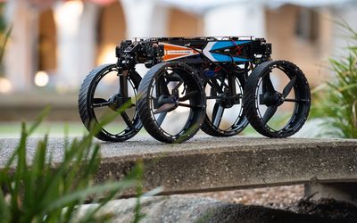
The Loper is a multi-purpose robotic platform using a Tri-lobe wheel design and a highly compliant chassis which makes the platform suited for overcoming challenges associated with search operations in urban settings. Each Tri-lobe wheel is coupleddirectly to a high torque, highly accurate AC servo actuator. The direct coupling of the wheels to the motors creates amechanically simple and robust system. The platform features long operational time, on-board sensor processing, dedicated motion control, and four reconfigurable sensor bays.
Technical Specifications
| Run time | 40 |
| Max speed | 8 |
| Climbing speed | 6 |
| Visual sensor |
Overview
The Loper is a multi-purpose robotic platform using a Tri-lobe wheel design and a highly compliant chassis which makes the platform suited for overcoming challenges associated with search operations in urban settings. Each Tri-lobe wheel is coupleddirectly to a high torque, highly accurate AC servo actuator. The direct coupling of the wheels to the motors creates amechanically simple and robust system. The platform features long operational time, on-board sensor processing, dedicated motion control, and four reconfigurable sensor bays.
The Loper control system is made of three off-the-shelf components: a dedicated motion controller, a PC-104 form factor computer, and a battery management system.
Mechanical design
The Tri-lobe wheels are designed to act as a cog when climbing a standard step, allowing it to climb steps with exceptional speed. The Tri-lobe wheel is a design inspired by the Lockheed Tri-star wheel. The Tri-star wheel features three wheels mounted to a central hub such that two of the attached wheels are normally on the ground. The simplest configuration provides drivepower to each of the wheels while allowing the central hubto rotate freely. The free rotation of the central hub allows the Tri-star wheel to rotate over obstacles as much as 75% the height of the whole Tri-star assembly. The mechanically simple Tri-lobe wheels are a modified Tri-star like hub without the attached wheels and sized to the task of stair climbing. The chassis and wheels were designed to with stand drops of up to 1.5 meters.
Chassis
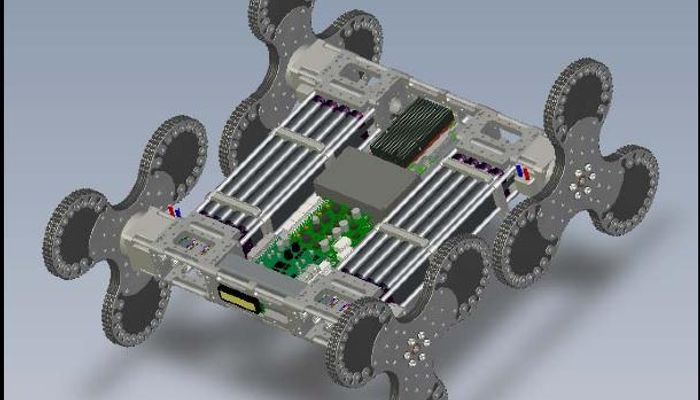
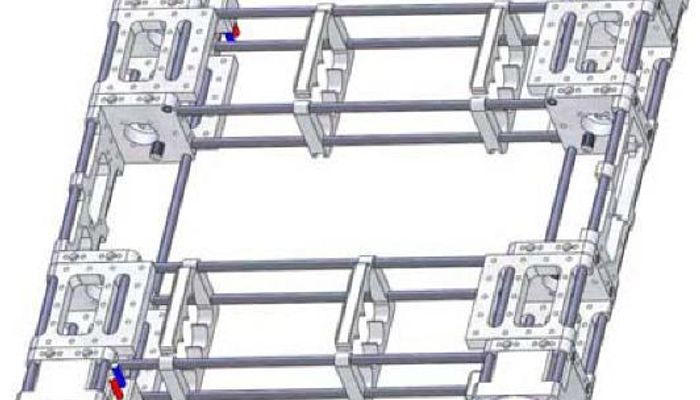
The main support structure for the chassis is the motor housings. Tool steel rods connect the motor housing and polyethylene plates provide mounting structures for electronics and additional plating or skin. The electronics hang from an aluminum plate in the center of the structure and are isolated from shock by rubber bushings in each corner. The motors are connected by steel rods to allow for twist between the left and right sides of the frame, creating a highly compliant structure capable to bending and flexing as needed to keep the Tri-lobe wheels in contact with the surface.
Electrical design
The electrical design is made up of five major components: a computer, motion controller, battery management circuit, eight lithium-ion smart batteries, and four servo actuators.
The computer has Ethernet for communications with the motion controller, 802.11g (Wi-Fi) and 802.15.1 (Bluetooth) for external communications. A flash drive is used as the boot device and as a mass storage device for data collection.
Each motor is capable of pulling 15 amps at 24 volts or 360 watts. The battery management system can handle high current at high discharge rates. The average power consumption is approximately 72 watts per motor which results in 288 watts of continues power draw while walking. Each motor is capable of drawing a peak power of 360 watts for up to two minutes.
References
Starts with a brief look at related works. The mechanical and electrical design are discussed. Reviews the control strategies utilized for stair climbing, walking, and turning. Provides some empirical results based on the implementation of the control strategies. Future work is discussed.
