ESP8266 Pinout: Unlocking the Power of IoT's Favorite Microcontroller
This article will guide you through the key features, functions, and configurations of the ESP8266 Pinout, setting the foundation for successful IoT implementations.

02 Sep, 2024. 17 minutes read
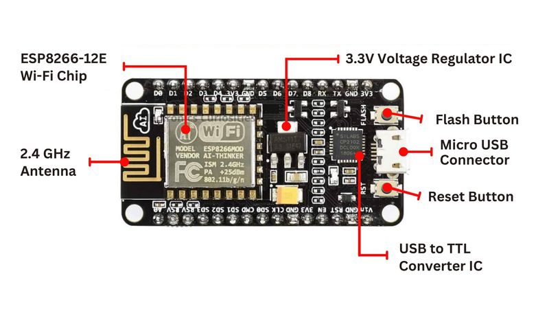
ESP8266 NodeMCU Board Labeled
Introduction
The ESP8266, a low-cost Wi-Fi microcontroller, has emerged as a cornerstone of the Internet of Things (IoT) revolution. This versatile chip combines Wi-Fi capabilities with processing power, making it an ideal choice for IoT applications, from smart home devices to industrial sensors. ESP8266 pinout determines the interaction of microcontroller with with various peripherals and sensors.
Understanding this ESP8266 pinout is essential for optimizing performance, ensuring reliable connections, and unlocking the full potential of this microcontroller. Each pin serves a specific purpose, and knowing how to utilize them correctly can mean the difference between a successful implementation and a frustrating debugging session. Proper pin management ensures optimal performance, power efficiency, and seamless integration with other components.
This comprehensive guide will provide a detailed exploration of the ESP8266 pinout, covering key features, power management, GPIO functionality, and communication interfaces. Whether you're a seasoned developer or just starting your IoT journey, mastering the pinout will empower you to create innovative and efficient IoT solutions.
The Heart of IoT: ESP8266 Unveiled
The ESP8266 chip offers a powerful combination of features that make it an ideal choice for a wide range of connected devices. At its core, the ESP8266 is a highly integrated Wi-Fi System-on-Chip (SoC) that provides a complete and self-contained Wi-Fi networking solution. [1]
One of the key reasons for the ESP8266's popularity in IoT applications is its remarkable balance of functionality, size, and cost. This tiny chip packs a punch, offering developers the ability to add Wi-Fi capabilities to their projects with minimal additional components. Its versatility has led to its adoption in smart home devices, wearables, industrial automation sensors, and countless other IoT applications.
The Wi-Fi capabilities of the ESP8266 are particularly noteworthy. It supports 802.11 b/g/n Wi-Fi standards, allowing for robust and reliable wireless communication. The chip can function as a station, access point, or both simultaneously, providing flexibility in network configuration. With its built-in TCP/IP stack, the ESP8266 can easily connect to existing Wi-Fi networks or create its own, enabling seamless integration into various IoT ecosystems.
In terms of processing power, the ESP8266 doesn't disappoint. It features a 32-bit RISC CPU running at 80 MHz (which can be overclocked to 160 MHz), providing enough computational resources for most IoT applications. This processing capability allows the chip to handle not only network communication but also complex sensor data processing and control logic. This eliminates the need for an additional microcontroller in many projects.
Key Features and Benefits of the ESP8266:
Wi-Fi Connectivity: The ESP8266 supports 802.11 b/g/n Wi-Fi standards, enabling robust and reliable wireless communication.
Processing Power: Its 32-bit RISC CPU, running at 80 MHz (overclockable to 160 MHz), provides ample computational resources for most IoT applications.
Memory: The ESP8266 offers 64 KB of instruction RAM and 96 KB of data RAM, sufficient for storing programs and data.
GPIO Pins: With 17 GPIO pins, the ESP8266 can easily interface with various sensors, actuators, and other peripherals.
Rich Peripheral Set: The ESP8266 includes GPIO pins, SPI, I2C, UART interfaces, and a 10-bit ADC, facilitating easy integration with various sensors and actuators.
Low Power Consumption: Its deep sleep mode (<10 µA) allows for minimal power consumption, making it suitable for battery-powered devices.
Versatility: The ESP8266 can function as a station, access point, or both, offering flexibility in network configurations.
Operating Voltage: It operates at a voltage range of 3.0V to 3.6V, making it compatible with a wide variety of power sources.
To put the ESP8266's capabilities into perspective, let's compare it with other popular IoT microcontrollers:
| Feature | ESP8266 | Arduino Uno | Raspberry Pi Zero W | Nordic nRF52840 |
| CPU | RISC 32-bit at 80 MHz | Atmel AVR 8-bit at 16 MHz | BCM2835 single core 64-bit at 1 GHz | ARM Cortex-M4 32-bit at 64 MHz |
| RAM | 160 KB | 2 KB | 512 MB | 256 KB |
| Wi-Fi | Built-in | Requires add-on | Built-in | Requires add-on |
| GPIO Pins | 16 | 14 | 40 | 48 |
| ADC | 10-bit | 10-bit | N/A | 12-bit |
| Price Range | $2 - $80 | $20 - $30 | $15 - $25 | $5 - $10 |
This comparison highlights the strengths of ESP8266 in terms of Wi-Fi integration, processing power, and cost-effectiveness, making it a compelling choice for many IoT applications. Its combination of features, along with a rich ecosystem of development tools makes it a go-to solution for IoT developers and enthusiasts.
Suggested Reading: ESP32 Pinout: A Comprehensive Guide for Engineers
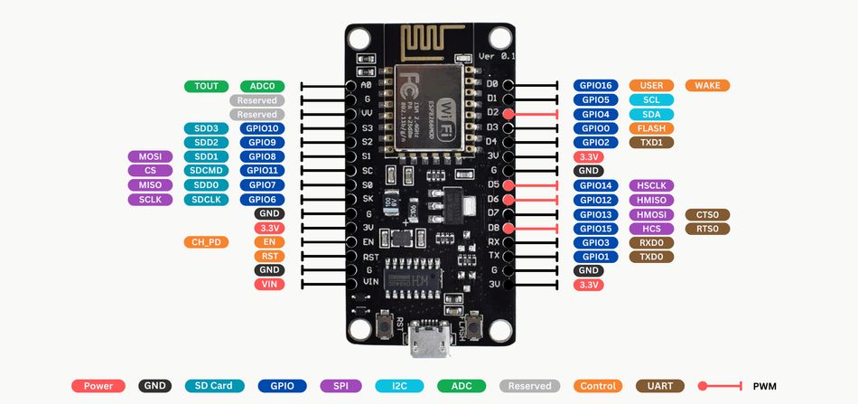
Decoding the ESP8266 Pinout Diagram
The ESP8266 comes in various modules, such as the ESP-01, ESP-12E, and NodeMCU, each with slightly different pin configurations. However, the fundamental principles of the pinout remain consistent across these versions. ESP8266 SoC is available in a 32-pin QFN Package (33 if we consider the center GND pad). [2]
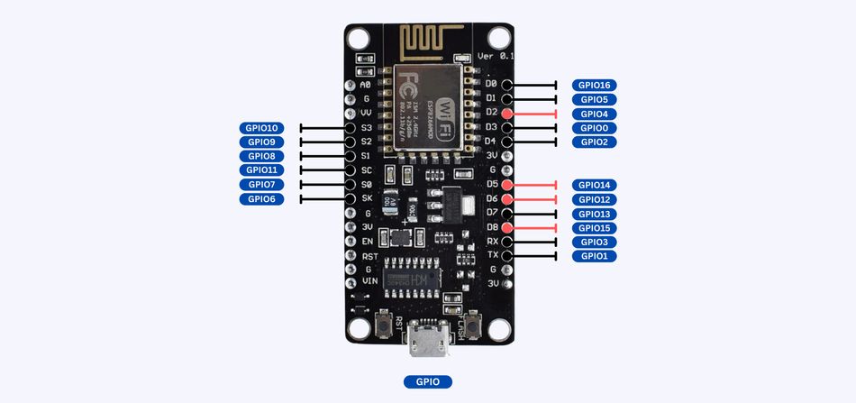
Central to its functionality is the pinout architecture, which defines how the microcontroller interfaces with external components and peripherals. Understanding this architecture is crucial for engineers looking to maximize the capabilities of ESP in their projects. Below are the key elements of ESP8266 pinout, focusing on the most commonly used module, the ESP-12E, which is often found in NodeMCU boards.
Significance of Each Pin Type
Within the ESP8266, a diverse range of pins exist, each serving distinct purposes critical to the operation of microcontroller. These include:
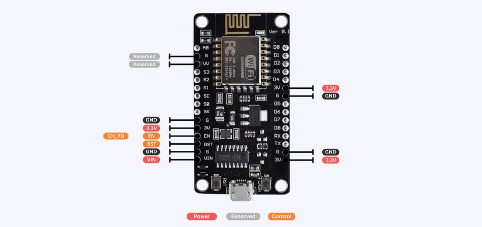
1. Power Pins (VCC, GND)
VIN or VCC (3V) is the power input pin, and it requires a stable 3V supply. The GND pin serves as the reference point for the voltage levels within the ESP8266 circuit.
2. General Purpose Input/Output (GPIO) Pins
The ESP8266 features 17 GPIO pins labeled GPIO0 to GPIO15 and GPIO16. These pins are versatile and can be configured as either input or output, depending on the application's needs. Each GPIO pin has specific capabilities and can perform multiple functions
3. Special Function Pins
ADC (A0): The ESP8266 includes a 10-bit analog-to-digital converter (ADC) on the A0 pin, allowing the microcontroller to read analog signals from sensors such as temperature or light sensors. The input range is typically 0 to 1V, so a voltage divider may be required to scale higher voltages.
RST (Reset): This pin is used to reset the microcontroller. Pulling this pin LOW will reset the ESP8266, causing it to restart the current program from the beginning.
EN (CH_PD): The enable pin must be pulled HIGH (connected to 3V) for the ESP8266 to run. Pulling it LOW puts the chip into a power-down state.
4. Power Management Pins
GPIO16 (D0) pin has a special role in power management. It is often used to wake the ESP8266 from deep sleep mode by connecting it to the RST pin. This feature is particularly useful in battery-powered applications where power conservation is crucial.
5. SPI Interface
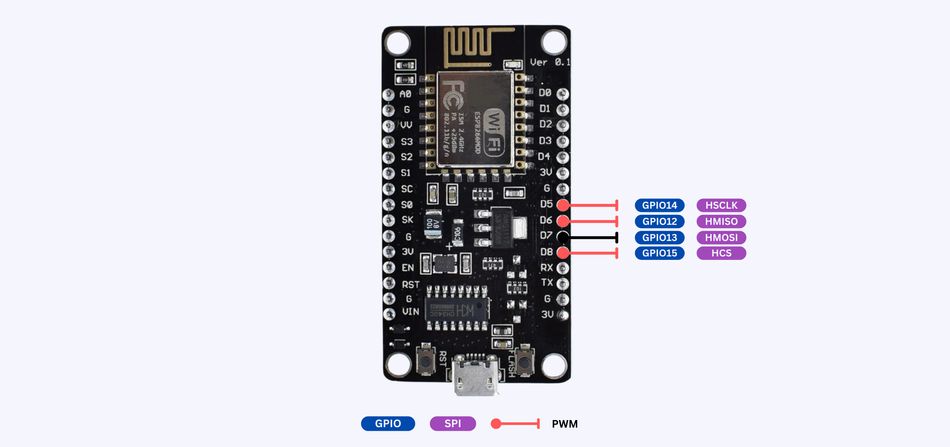
The Serial Peripheral Interface (SPI) is a communication protocol commonly used for interfacing the ESP8266 with flash memory, sensors, and other modules. GPIO12 (MISO), GPIO13 (MOSI), GPIO14 (SCLK), and GPIO15 (CS) pins are dedicated to SPI communication, but they can be repurposed if SPI is not being used.
6. I2C Interface
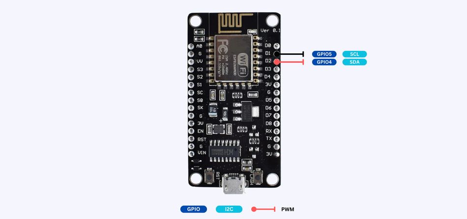
GPIO4 (SDA) & GPIO5 (SCL) pins support I2C communication, a popular protocol for interfacing with multiple sensors and modules using just two wires. These I2C pins allow multiple devices to communicate with the ESP8266, making it ideal for complex IoT projects.
7. UART Interface
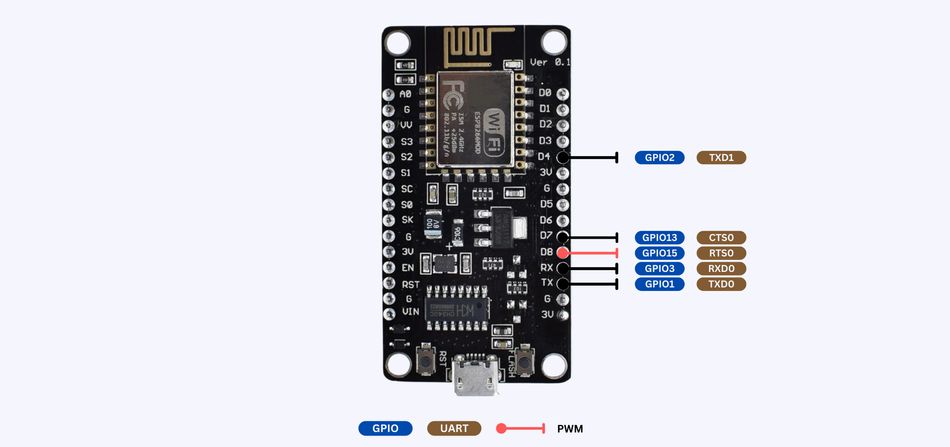
The Universal Asynchronous Receiver/Transmitter (UART) interface is used for serial communication, essential for debugging and flashing firmware. GPIO1 (TX pin) & GPIO3 (RX pin) are typically connected to a USB-to-serial adapter when programming the ESP8266.
8. PWM Pins
GPIO12, GPIO13, and GPIO14 pins support Pulse Width Modulation (PWM), which is used to control the brightness of LEDs, speed of motors, and other similar applications. The ESP8266 can generate PWM signals on these pins with up to 10-bit resolution.
9. External Interrupts
GPIO0, GPIO2, GPIO4, GPIO5, GPIO12, GPIO13, GPIO14, and GPIO15 pins can also be used as external interrupt sources, allowing the ESP8266 to respond to external events such as a button press.
10. Deep Sleep Wakeup Pin
GPIO16 (D0) pin is connected to the RST pin to wake the ESP8266 from deep sleep mode. This pin is crucial for projects where power efficiency is important, such as battery-operated IoT devices.
Mastering the ESP8266 Pinout Diagram
To effectively read and interpret the ESP8266 pinout diagram, follow these steps:
Start by identifying the power pins (VCC and GND) as these are critical for proper operation.
Locate the GPIO pins, which are your primary interface for connecting sensors and actuators.
Pay attention to pins with multiple functions, often indicated by slash-separated labels (e.g., GPIO2/TXD1).
Note any pins with specific requirements, such as pull-up or pull-down resistors.
Identify the communication interface pins (UART, SPI, I2C) for connecting to other devices.
Familiarize yourself with common acronyms used in the ESP8266 pinout to better understand the function of each pin:
GPIO: General Purpose Input/Output
VCC: Voltage Common Collector (power supply)
GND: Ground
RX/TX: Receive/Transmit (for UART communication)
SPI: Serial Peripheral Interface
I2C: Inter-Integrated Circuit
ADC: Analog-to-Digital Converter
CH_PD: Chip Power-Down (active-high enable)
Understanding these acronyms and their functions is essential for correctly interpreting the pinout diagram and designing your ESP8266-based circuits. Some pins have multiple functions, and their behavior may change depending on the chip's operating mode or your programming.
Suggested Reading: I2C vs SPI: A Comprehensive Comparison and Analysis
Pin Functions: Your Gateway to ESP8266 Mastery
Power Pins: Energizing Your ESP8266
The ESP8266 requires careful attention to its power requirements for optimal performance and longevity. This versatile chip operates within a narrow voltage range of 3.0V to 3.6V, with a nominal input voltage of 3V. The current draw can vary significantly depending on the operating mode, ranging from a few microamps in deep sleep to over 300mA during transmission bursts.
Key power-related pins on the ESP8266 include:
VCC (Voltage Common Collector): This is the main power input pin. It should be connected to a stable 3.3V power source capable of supplying up to 500mA for reliable operation.
GND (Ground): Multiple GND pins are typically available on the ESP8266 module. These should all be connected to the circuit's ground plane to ensure proper grounding and noise reduction.
CH_PD (Chip Power-Down): This pin acts as an enable pin for the ESP8266. It must be pulled high (connected to VCC) for the chip to operate. Pulling this pin low will put the chip into a low-power state.
Best practices for powering the ESP8266 safely include:
Use a dedicated 3.3V voltage regulator capable of handling the peak current demands.
Implement proper decoupling with capacitors close to the VCC and GND pins. A 10µF electrolytic capacitor in parallel with a 100nF ceramic capacitor is often recommended.
Ensure all GND pins are connected to a solid ground plane.
When using battery power, implement a low-dropout (LDO) regulator to maintain stable voltage as the battery discharges.
Consider using a level shifter when interfacing with 5V devices to protect the pins of your ESP8266.
Proper power management is crucial for the ESP8266. Exceeding the maximum voltage rating or failing to provide adequate current can lead to erratic behavior, reduced Wi-Fi performance, or permanent damage to the chip. Always double-check your power supply connections and ratings before powering up your ESP8266-based project. Implementing brownout detection in your firmware can also help prevent issues caused by voltage fluctuations.
GPIO Pins: The Versatile Workhorses
General Purpose Input/Output (GPIO) pins are the primary interface between the ESP8266 and the physical world in IoT projects. These versatile pins can be programmed to either read input signals or control output devices. This makes them essential for tasks such as reading sensor data, controlling LEDs, or interfacing with other electronic components.
The ESP8266 offers 17 GPIO pins, although not all are typically available for general use due to various factors such as board design or internal functions. [3] The available GPIO pins are labeled GPIO0 to GPIO15, and GPIO16. Many of these GPIO pins serve multiple functions, which adds to their versatility but also requires careful consideration during project design. For example, some pins are used for the SPI interface, while others are involved in the boot process or UART communication.
Below is a detailed table that outlines ESP8266 GPIO pins, their alternate functions, and specific notes on their usage:
| GPIO Pin | Alternate Function | Special Considerations |
| GPIO0 | Boot Mode Selection | Must be HIGH on Boot for Normal Operation |
| GPIO1 | UART0_TXD | Commonly used for Serial Communication |
| GPIO2 | UART1_TXD | Must be HIGH on the Boot |
| GPIO3 | UART0_RXD | Often used for Serial Communication |
| GPIO4 | SPI_CS1 | General Purpose I/O |
| GPIO5 | SPI_CS0 | General Purpose I/O |
| GPIO6-11 | Connected to Flash Memory | Not Generally Available for External Use |
| GPIO12 | HSPI_MISO | General Purpose I/O |
| GPIO13 | HSPI_MOSI | General Purpose I/O |
| GPIO14 | HSPI_CLK | General Purpose I/O |
| GPIO15 | UART0_RTS | Must be LOW on the Boot |
| GPIO16 | Wake Up from Deep Sleep | Limited Functionality |
Key Points to Remember:
GPIO0 and GPIO2 must be handled carefully during the boot process; incorrect states can prevent the ESP8266 from booting properly.
GPIO15 should be pulled low during boot; otherwise, the chip might fail to start.
GPIO6 to GPIO11 are internally connected to the flash memory of the ESP8266 and are not typically available for general I/O purposes.
GPIO16 has limited functionality and is primarily used to wake the ESP8266 from deep sleep, which is essential for power-sensitive applications.
To configure and use GPIO pins in your ESP8266 projects, you'll typically use a framework like Arduino or ESP-IDF. Here are some code snippets demonstrating basic GPIO operations using the Arduino framework:
1. Configuring a Pin as an Output and setting its State:
const int ledPin = 2;  // GPIO2

void setup() {
  pinMode(ledPin, OUTPUT);  // Set the pin as an output
}

void loop() {
  digitalWrite(ledPin, HIGH);  // Turn the LED on
  delay(1000);
  digitalWrite(ledPin, LOW);   // Turn the LED off
  delay(1000);
}
This code will make the LED connected to GPIO2 blink ON and OFF every second.
2. Reading the State of an Input Pin:
const int buttonPin = 0;  // GPIO0
int buttonState = 0;

void setup() {
  pinMode(buttonPin, INPUT_PULLUP);  // Set the pin as an input with internal pull-up resistor
  Serial.begin(115200);
}

void loop() {
  buttonState = digitalRead(buttonPin);
  Serial.println(buttonState);
  delay(100);
}
This code will work as:
When the button is not pressed, buttonState will be HIGH (1) because of the internal pull-up resistor.
When the button is pressed, buttonState will be LOW (0) because the button connects GPIO0 directly to the ground.
3. Using PWM (Pulse Width Modulation) on a GPIO pin:
const int pwmPin = 5;  // GPIO5
int pwmValue = 0;

void setup() {
  pinMode(pwmPin, OUTPUT);
}

void loop() {
  for (pwmValue = 0; pwmValue <= 1023; pwmValue++) {
    analogWrite(pwmPin, pwmValue);  // Set PWM duty cycle (0 to 1023)
    delay(10);
  }
  for (pwmValue = 1023; pwmValue >= 0; pwmValue--) {
    analogWrite(pwmPin, pwmValue);  // Set PWM duty cycle (0 to 1023)
    delay(10);
  }
}
This code will work as:
It gradually increases the PWM value from 0 (OFF) to 1023 (fully ON) over a period of time, making the LED (or other connected device) gradually brighten.
Then, it gradually decreases the PWM value back to 0, making the LED dim back down.
The delay of 10 milliseconds creates a smooth transition in brightness.
When working with GPIO pins, it's crucial to consider their alternate functions and any special requirements, such as boot mode restrictions. Always refer to the ESP8266 datasheet and the documentation of your module to ensure proper pin usage and avoid conflicts with essential system functions.
Communication Interfaces: Connecting Your ESP8266 to the World
The ESP8266 supports multiple communication interfaces, enabling it to interact with a wide range of sensors, actuators, and other microcontrollers. The three primary interfaces are UART (Universal Asynchronous Receiver/Transmitter), SPI (Serial Peripheral Interface), and I2C (Inter-Integrated Circuit).
1. UART (Universal Asynchronous Receiver/Transmitter)
UART is a straightforward, two-wire serial communication protocol that is widely used for simple and reliable data transmission between devices. The ESP8266 has two UART interfaces:
UART0: GPIO1 (TX) and GPIO3 (RX)
UART1: GPIO2 (TX only)
Pros:
Ease of Implementation: UART is easy to set up and use, making it ideal for beginners and quick prototyping.
Debugging-Friendly: The simplicity of UART makes it easier to debug compared to more complex protocols.
Full-Duplex Communication: UART0 supports full-duplex communication, allowing simultaneous transmission and reception of data.
Cons:
One-to-One Communication: UART is typically limited to communication between two devices, which can be a drawback in more complex systems.
Lower Speed: Compared to other protocols like SPI, UART offers lower data transfer speeds.
Timing Sensitivity: Without a clock signal, UART requires precise timing, which can be a challenge in noisy environments.
Practical Example: Connecting the ESP8266 to a GPS module to receive real-time location data.
Code snippet for UART communication:
void setup() {
  Serial.begin(115200);  // Initialize UART0 at 115200 baud rate
}

void loop() {
  if (Serial.available()) {
    char c = Serial.read();
    Serial.print("Received: ");
    Serial.println(c);
  }
}
This code will work as:
When you send a character from your computer (using the Serial Monitor in the Arduino IDE, for example), the ESP8266 receives that character via UART0.
The received character is read using Serial.read() and then printed back to the Serial Monitor with a "Received: " prefix, allowing you to confirm that the character was successfully received.
2. SPI (Serial Peripheral Interface)
SPI is a high-speed, synchronous serial communication protocol that uses a master-slave architecture, making it well-suited for applications requiring fast data transfer. The ESP8266 supports SPI with the following pins:
MOSI (Master Out Slave In): GPIO13
MISO (Master In Slave Out): GPIO12
SCLK (Serial Clock): GPIO14
CS (Chip Select): GPIO15 (or any available GPIO)
Pros:
High-Speed Communication: SPI is capable of very high data transfer rates, making it ideal for applications like data streaming or fast sensors.
Full-Duplex Communication: SPI supports simultaneous data transmission and reception.
Multi-Slave Support: Multiple slave devices can be connected to a single master, allowing complex systems to be built with minimal effort.
Cons:
Increased Pin Usage: SPI requires more pins than I2C, which can be a limitation in pin-constrained designs.
No Built-in Flow Control: Unlike I2C, SPI does not have built-in mechanisms for flow control or acknowledgment, which can complicate error handling.
Practical Example: Interfacing the ESP8266 with an SD card for high-speed data logging.
Code snippet for SPI communication:
#include <SPI.h>

const int ssPin = 15;  // Set to the correct GPIO pin for SS on-board

void setup() {
  pinMode(ssPin, OUTPUT);
  SPI.begin();
  SPI.setClockDivider(SPI_CLOCK_DIV8);  // Set SPI clock
}

void loop() {
  digitalWrite(ssPin, LOW);  // Select slave device
  SPI.transfer(0x55);        // Send data
  digitalWrite(ssPin, HIGH); // Deselect slave device
  delay(1000);
}
This code sets up the ESP8266 to communicate with a slave device over SPI, sending a byte (0x55) every second.
3. I2C (Inter-Integrated Circuit)
I2C is a versatile, two-wire serial protocol that allows multiple slave devices to communicate with one or more master devices on the same bus. The ESP8266 uses the following pins for I2C:
SDA (Serial Data): GPIO4
SCL (Serial Clock): GPIO5
Pros:
Minimal Wiring: I2C requires only two wires to connect multiple devices, making it efficient and easy to wire.
Supports Multiple Devices: With its built-in addressing system, I2C can manage communication with multiple devices on the same bus.
Hot-Swapping: Devices can be added or removed from the bus without disrupting communication, adding flexibility to your design.
Cons:
Slower Data Transfer: I2C is generally slower than SPI, which may be a limitation for high-speed applications.
Limited Cable Length: The shared bus can only extend so far due to bus capacitance, limiting the distance between devices.
Practical Example: Connecting multiple sensors, such as temperature, humidity, and pressure sensors, to a single ESP8266 for environmental monitoring.
Code snippet for I2C communication:
#include <Wire.h>
void setup() {
  Wire.begin();  // Initialize I2C as master
  Serial.begin(115200);  // Initialize serial communication for debugging
}
void loop() {
  Wire.beginTransmission(0x68);  // Start transmission to device address 0x68
  Wire.write(0x00);              // Send register address
  byte status = Wire.endTransmission(false);  // End transmission but keep connection     active

  if (status == 0) {  // Transmission successful
    Wire.requestFrom(0x68, 1);     // Request 1 byte from slave device
    if (Wire.available()) {
      byte data = Wire.read();     // Read received data
      Serial.println(data);        // Print the received data for debugging
      // Process data
    }
  } else {
    Serial.println("Transmission failed");
  }
  delay(1000);
}
This code is designed to communicate with an I2C device connected to the ESP8266, specifically a device with the I2C address 0x68 (which is commonly used by devices like the MPU6050 accelerometer/gyroscope).
Each communication interface has its strengths and is suited for different applications. UART is ideal for simple, direct connections; SPI excels in high-speed data transfer scenarios; and I2C is perfect for connecting multiple low-speed peripherals with minimal pin usage. By understanding these interfaces, you can effectively integrate the ESP8266 into a wide range of IoT projects, from simple sensor readings to complex multi-device systems.
Suggested Reading: UART vs I2C (vs SPI): Understanding the Differences
Programming Considerations: Maximizing ESP8266 Performance
When programming the ESP8266, several factors must be considered to ensure optimal performance and reliability. The limited resources, unique architecture, and Wi-Fi capabilities of the chip require careful planning and optimization.

One of the most critical aspects of ESP8266 programming is understanding the bootloader pins. The ESP8266 uses GPIO0, GPIO2, and GPIO15 to determine the boot mode:
GPIO0: Pull low for flashing mode, high for normal boot
GPIO2: Must be pulled high for both flashing and normal boot
GPIO15: Must be pulled low for both flashing and normal boot
Proper configuration of these pins is essential for successful programming and operation of the ESP8266.
To optimize code for the limited resources of ESP8266:
Use efficient data types and avoid unnecessary variables
Implement sleep modes to conserve power when possible
Utilize the hardware capabilities of ESP8266, such as hardware timers and interrupts
Minimize string operations and use F() macro for constant strings
Optimize Wi-Fi usage by implementing deep sleep between transmissions
Here's a table of recommended programming environments and tools for ESP8266 development:
| Tool/Environment | Description | Best For |
| Arduino IDE | User-friendly IDE with ESP8266 Support | Beginners, Quick Prototyping |
| PlatformIO | Professional IDE with Advanced Features | Experienced Developers, Large Projects |
| ESP-IDF | Espressif's Official Development Framework | Low-level Control, Advanced Users |
| NodeMCU | Lua-based Firmware for Rapid Development | Scripting Enthusiasts, Quick IoT Projects |
| MicroPython | Python Implementation for Microcontrollers | Python Developers, Educational Projects |
Best practices for debugging ESP8266-based projects include:
Use serial output for basic debugging, but be mindful of its impact on timing-sensitive operations
Implement error handling and logging mechanisms to capture and report issues
Utilize over-the-air (OTA) updates to facilitate remote debugging and updates
Employ hardware debugging tools like logic analyzers for complex timing issues
Implement watchdog timers to recover from potential crashes or hangs
Use assertions and runtime checks to catch errors early in the development process
Leverage ESP8266-specific debugging features, such as ESP Exception Decoder for stack traces
By considering these programming factors developers can maximize the performance and reliability of their ESP8266-based projects. This approach ensures that the full potential of this versatile chip is realized in various IoT applications.
Recommended Reading: Microcontroller-Based IoT Development Kits: Powering the Next Generation of IoT Solutions
Conclusion
The ESP8266 has emerged as a powerful and versatile microcontroller for IoT development. Understanding its pinout is essential for effectively connecting external components and creating innovative projects. By mastering the GPIO pins, communication interfaces, and programming considerations, developers can create sophisticated IoT solutions that are both efficient and reliable.
To solidify your understanding and gain practical experience, consider exploring a variety of IoT projects, from smart home systems to environmental data loggers. Experimentation will not only enhance your skills but also inspire you to create unique and impactful IoT solutions.
Frequently Asked Questions
Q: How do pinouts differ between various ESP8266 models?
A: While the core ESP8266 chip has a standard pinout, different development boards (e.g., NodeMCU, Wemos D1 Mini) may have varying pin arrangements. Always refer to the tutorials and documentation of the specific board for accurate pinout information.
Q: How compatible is the ESP8266 with sensors designed for other microcontrollers?
A: The ESP8266 is generally compatible with many I2C and SPI sensors designed for 3.3V operation. However, 5V sensors may require level shifters, and some Arduino-specific libraries may need adaptation.
Q: Can I use all GPIO pins simultaneously in a project?
A: While theoretically possible, it's not recommended to use all GPIO pins simultaneously. Some pins have special functions or restrictions, and using too many can lead to increased power consumption and potential conflicts.
Q: How can I protect the ESP8266 pins from damage during development?
A: To protect the pins:
Always use appropriate resistors for LED circuits
Implement level shifters when interfacing with 5V devices
Be cautious of static electricity when handling the board
Use current-limiting resistors or relays on analog input pins
Double-check the wiring before powering on the circuit
References
[1] Espressif. ESP8266 Wi-Fi SoC Details [Cited 2024 August 28] Available at: Link
[2] Espressif. ESP8266 Wi-Fi SoC Documentation and Pinout Reference [Cited 2024 August 28] Available at: Link
[3] ResearchGate. Internet of Things and NodeMCU: A review of Use of NodeMCU ESP8266 in IoT products [Cited 2024 August 28] Available at: Link
Table of Contents
IntroductionThe Heart of IoT: ESP8266 UnveiledDecoding the ESP8266 Pinout DiagramSignificance of Each Pin TypeMastering the ESP8266 Pinout DiagramPin Functions: Your Gateway to ESP8266 MasteryPower Pins: Energizing Your ESP8266GPIO Pins: The Versatile WorkhorsesCommunication Interfaces: Connecting Your ESP8266 to the WorldProgramming Considerations: Maximizing ESP8266 PerformanceConclusionFrequently Asked QuestionsReferences