I3C vs I2C: Unraveling the Battle of Communication Protocols
I3C is becoming a strong alternative to I2C. Learn about the main differences, benefits, and uses of these two important communication protocols. Explore the world of inter-integrated circuit communication and see which protocol is best for your next project.

26 Jul, 2024. 20 minutes read
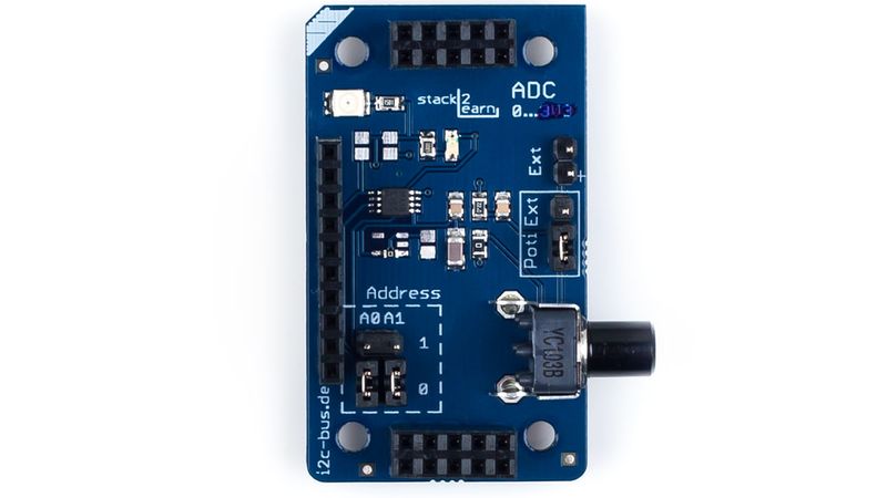
ADC Module using I2C interface
In embedded systems, good communication protocols are key for smooth device interaction. The Inter-Integrated Circuit (I2C) protocol has been widely used for its simple and effective way of exchanging data between circuits. But as technology improves and we need faster, more energy-efficient communication, the Improved Inter-Integrated Circuit (I3C) has become a strong alternative.
I3C is built on I2C bus, offering faster speeds, lower power use, and extra features, while still being compatible with I2C. As embedded systems get more complex, it's important for engineers and designers to understand both I2C and I3C. Choosing the right protocol can greatly affect system performance, energy efficiency, and scalability. By looking at the main differences, benefits, and uses of I2C and I3C, we can better understand the changing world of embedded system communication and make better choices for future designs.
Decoding the Alphabet Soup: I2C and I3C Explained
The Legacy of I2C: A Time-Tested Protocol
The Inter-Integrated Circuit (I2C) protocol, developed by Philips Semiconductors in the early 1980s has become a cornerstone of embedded system communication. This serial communication protocol operates on a simple yet effective principle of synchronous data transfer between integrated circuits.
I2C Operation
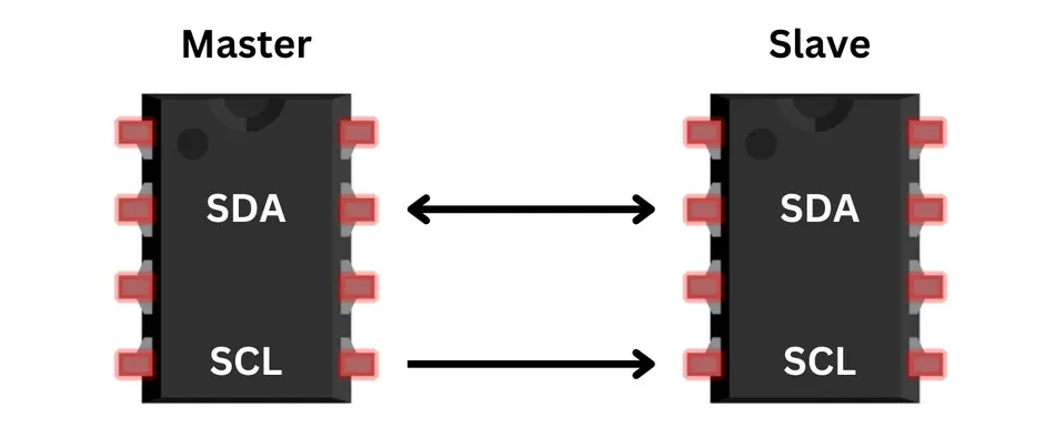
At its core, I2C bus utilizes a two-wire system for bidirectional communication:
- The Serial Data Line (SDA) carries the actual data being transmitted.
- The Serial Clock Line (SCL) provides the timing signal that synchronizes the data transfer.
This elegant design allows for efficient communication with minimal pin usage on integrated circuits.
- Start: I2C employs a master-slave architecture, where one or more master devices initiate and control the communication with multiple slave devices. The master generates the clock signal by pulling the SDA line from high to low while the SCL line remains high. This signals all I2C slave devices that a transmission is starting.
- Address Frame: After the start condition, the master sends an address frame, which is typically 7 or 10 bits long. This frame identifies the slave device that the master intends to communicate with. The address is followed by a bit indicating the operation (read or write – 0 for write, 1 for read) [1].
- Acknowledgment: After receiving the address, if the addressed I2C slave device is present on the bus, it responds with an acknowledgment signal (ACK). This is done by pulling the SDA line low during the ninth clock pulse.
- Stop: The master terminates the communication by issuing a stop condition. This involves transitioning the SDA line from low to high while the SCL line is high.
- Clock Stretching [2]: Slaves can control the flow of communication by holding the SCL line low after receiving or sending a byte, indicating they are not ready to proceed. The master must wait until the SCL line is released (goes high) before continuing.
- The I2C protocol supports various speed modes to accommodate different application requirements. The standard mode operates at 100 kbit/s, while the fast mode pushes speeds up to 400 kbit/s. For more demanding applications, the fast mode plus can achieve 1 Mbit/s, and the high-speed mode tops out at 3.4 Mbit/s.
Additional features of I2C
- Multi-master configuration: More than one master can initiate communication. The arbitration process determines which master controls the bus.
- Built-in collision detection: The process of identifying when two or more masters start a transmission at the same time or when a master attempts to transmit while another master is already using the bus.
- Arbitration: If two masters simultaneously start communication, the one transmitting a lower address bit (0) while the other transmits a high (1) wins the arbitration and continues with the message. The losing master must wait until the bus is free again.
- Bi-directional data transfer on a single SDA line.
- 7-bit or 10-bit addressing, supporting up to 128 or 1024 devices on a single bus.
- Software-addressable devices, eliminating the need for chip-select lines.
- Scalability, allowing easy addition or removal of devices from the bus.
- Low power consumption due to its simple electrical specifications.
The MIPI I3C Inception
The Improved Inter-Integrated Circuit (I3C) protocol represents a significant evolution of the well-established I2C standard. Developed by the MIPI Alliance, I3C aims to address the growing demands of modern embedded systems while building upon the simplicity and widespread adoption of I2C.
The primary motivation behind I3C's development was the need for a more versatile and efficient communication protocol in increasingly complex and power-sensitive devices. As sensor integration in mobile and IoT devices grew, limitations in I2C's speed, power consumption, and feature set became apparent. I3C was designed to overcome these limitations while maintaining familiarity for developers accustomed to I2C.
I3C operation
Below are a few unique operational features of I3C, as compared to I2C:
- Addressing and Commands: The communication begins similarly to I2C. After that, the master sends a command frame that includes the device address and a common command code. The address could be dynamically assigned if it’s the first communication with that device.
- Data Transfer: Data is sent in data frames following the command frame. I3C introduces more structured and efficient data frames compared to I2C, enabling better error handling and more complex communication patterns.
Additional I3C Features
- Dynamic Address Assignment: Upon initialization, devices (I3C slaves) do not need preconfigured addresses. The master can assign addresses dynamically, which helps manage more devices on the bus efficiently.
- Hot-Join Mechanism: New devices can join the bus while it is active. This feature is crucial for systems where devices might be hot-swapped.
- In-Band Interrupts: Slaves can signal the master using the same data line (SDA) about specific needs or alerts, which is a significant enhancement over I2C, eliminating the need for separate interrupt lines.
One of I3C's key strengths is its backward compatibility with I2C. This allows for a smooth transition in existing systems and enables the coexistence of I2C and I3C devices on the same bus. I3C controllers can communicate with I2C devices using the legacy protocol, facilitating a gradual migration path for manufacturers and reducing the need for immediate, wholesale system redesigns.
I3C brings several significant improvements over its predecessor [3]. It offers substantially higher data rates, with a maximum speed of 12.5 MHz in the base specification and up to 100 MHz in the High Data Rate (HDR) mode. Power efficiency is enhanced through lower operating voltages and in-band interrupt capabilities, reducing the need for additional interrupt lines. I3C also introduces dynamic addressing, eliminating address conflicts and simplifying system configuration.
| Feature | I2C | I3C |
| Maximum Clock Speed | 3.4 MHz (High-speed mode) | 12.5 MHz (Base), 100 MHz (HDR) |
| Bitrate [2] | Upto 3.3 Mbps | Upto 33.3 Mbps |
| Addressing | Static, 7 or 10-bit | Dynamic, 7-bit |
| Multi-master Support | Limited | Enhanced with role-handoff |
| In-band Interrupts | No | Yes |
| Hot-join Capability | No | Yes |
| Backward Compatibility | - | With I2C |
| Voltage Range | 1.8V to 5V | 1.2V to 3.3V |
| Error Detection | Basic (ACK/NACK) | Advanced (CRC, Parity) |
This table provides a concise comparison of the basic features between I2C and I3C, highlighting the significant advancements offered by the newer protocol.
While i2c bus and mipi i3c are essential protocols, embedded systems often require the integration of various other communication protocols like Serial Peripheral Interface (SPI) and uart (Universal Asynchronous Receiver-Transmitter). These protocols cater to different aspects of device communication, ensuring a versatile and robust system design.
Recommended Readings: I2C vs SPI: A Comprehensive Comparison and Analysis
Recommended Readings: UART vs SPI: A Comprehensive Comparison for Embedded Systems
I3C vs I2C: Speed Comparison
Clock Frequencies and Data Rates
The I2C protocol offers multiple speed modes to cater to various application needs.
- The Standard-mode operates at 100 kbit/s, providing a reliable baseline for many applications.
- The Fast-mode pushes this to 400 kbit/s, offering improved performance for more demanding scenarios.
- For even higher speeds, the Fast-mode Plus reaches 1 Mbit/s, while the High-speed mode tops out at 3.4 Mbit/s.
These higher speeds enable I2C to handle more data-intensive tasks, though they require compatible hardware.
I3C, designed as a successor to I2C, introduces more advanced speed capabilities [4].
- Its Standard Data Rate (SDR) mode already matches I2C's Fast-mode Plus at 12.5 Mbit/s, providing a significant boost in baseline performance.
- I3C's High Data Rate (HDR) modes take this further, with HDR-DDR (Double Data Rate) reaching 25 Mbit/s.
- HDR-TSP (Ternary Symbol Pure) hitting 33.3 Mbit/s.
These modes allow I3C to handle much larger data transfers efficiently.
| Feature | I2C Speed (Mbit/s) | I3C Speed (Mbit/s) |
| Standard Mode | 0.1 | 12.5 |
| Fast Mode | 0.4 | N/A |
| Fast Mode Plus | 1.0 | N/A |
| High-Speed Mode | 3.4 | N/A |
| SDR Mode | N/A | 12.5 |
| HDR-DDR Mode | N/A | 25.0 |
| HDR-TSP Mode | N/A | 33.3 |
These speed improvements have significant real-world implications. In mobile and IoT devices, where I3C finds extensive use, the higher data rates allow for faster sensor readings and more responsive systems. This is crucial in applications like augmented reality or real-time health monitoring, where rapid data processing is essential. The increased speeds also enable the connection of more devices on a single bus without sacrificing performance, leading to simpler and more efficient system designs. For industrial applications, the higher speeds of both advanced I2C modes and I3C facilitate quicker control responses and more detailed data collection, enhancing overall system efficiency and capabilities.
Latency and Efficiency
I3C demonstrates significantly lower latency compared to I2C, primarily due to its higher clock speeds and more efficient signaling method. While I2C typically operates with latencies in the microsecond range, I3C can achieve latencies in the nanosecond range, enabling faster response times in time-sensitive applications.
Data transfer efficiency is markedly improved in I3C. The protocol's ability to transfer data at higher speeds, coupled with its more sophisticated addressing and interrupt mechanisms, allows for more data to be transmitted in less time compared to I2C. This efficiency is particularly evident in sensor-rich environments where frequent, small data transfers are common.
I3C's push-pull signaling represents a significant advancement over I2C's open-drain signaling. In I2C, the bus is pulled high by a resistor and driven low by devices, which limits speed and increases power consumption. I3C's push-pull signaling actively drives the bus both high and low, reducing rise and fall times, thereby allowing for faster data rates and lower power consumption. This improvement is especially beneficial in battery-powered devices where energy efficiency is crucial.
Factors affecting latency in both protocols include:
- Bus capacitance and length
- Number of devices on the bus
- Clock speed and data rate
- Addressing method and overhead
- Error detection and correction mechanisms
- Protocol-specific features (e.g., I3C's in-band interrupts)
Power Play: Energy Efficiency Face-off
Power Consumption Analysis
I3C demonstrates significantly lower power consumption compared to I2C across various operating modes. In standard operation, I3C consumes approximately 5 to 18 times less energy than I2C to transfer 1 kilobyte of data. This efficiency gap widens further in high-speed modes, where I3C's advanced features come into play [5] (Check reference for graph stats).
I3C's design incorporates several power-saving features. The protocol uses push-pull signaling for data transfer, which actively drives the bus both high and low. This approach reduces power consumption compared to I2C's open-drain signaling, which relies on pull-up resistors to bring the bus high. I3C also supports in-band interrupts, eliminating the need for additional interrupt lines and reducing overall power draw.
In I2C systems, pull-up resistors significantly impact power consumption. These resistors continuously draw current when the bus is in its idle (high) state, leading to constant power drain. The strength of these pull-ups affects both power consumption and signal integrity, creating a challenging trade-off for designers.
In a typical smartwatch scenario, replacing I2C with I3C for sensor communication could extend battery life by up to 30%. In IoT devices that rely on infrequent, burst data transmissions, the power savings are even more pronounced. A battery-powered environmental sensor using I3C instead of I2C could potentially operate for months longer on a single charge, reducing maintenance needs and improving overall system reliability.
Sleep Modes and Wake-up Mechanisms
I2C and I3C both offer sleep modes to conserve power in embedded systems, but their implementations differ significantly.
In I2C, devices enter a low-power state where the clock is stopped and most internal circuits are powered down. I3C provides more sophisticated sleep modes, including a deep sleep state where only essential circuitry remains active. Wake-up mechanisms in I2C typically involve an external interrupt or a specific bus condition. The master device initiates communication, causing slave devices to wake up and respond.
I3C, on the other hand, offers more flexible wake-up options, including its innovative in-band interrupt feature. I3C's in-band interrupt capability allows slave devices to signal the master without additional dedicated interrupt lines. This feature enables devices to request attention or indicate data availability while in sleep mode, reducing system complexity and power consumption. It also allows for more responsive and efficient communication, as devices can initiate interactions based on internal events or sensor readings.
| Protocol | Sleep Mode Current | Wake-up Time | Interrupt Lines Required |
| I2C | 1-10 µA | 100-500 µs | Yes |
| I3C | 0.1-1 µA | 10-50 µs | No (uses in-band) |
Wake-up process for I2C:
- Master device initiates communication by generating a START condition
- Slave devices detect the START condition on the bus
- Slave devices power up their internal circuitry
- Slaves check the address sent by the master
- If the address matches, the slave responds and enters active mode
Wake-up process for I3C:
- Slave device generates an in-band interrupt (IBI) request
- Master detects the IBI and acknowledges it
- Slave device sends its dynamic address and status byte
- Master processes the interrupt and initiates appropriate action
- Slave device enters active mode and begins normal communication
Feature Frenzy: Capabilities and Limitations
Addressing Schemes
I2C employs two addressing methods: 7-bit and 10-bit. The 7-bit addressing scheme, the most common, allows for 128 unique addresses (2^7), with some reserved for special purposes. The 10-bit addressing expands this to 1024 unique addresses (2^10), providing more flexibility for complex systems. In practice, the 7-bit address is sent in the first byte after the start condition, with the eighth bit used as the read/write flag. For 10-bit addressing, a special prefix is used, followed by the remaining address bits.
I3C introduces dynamic addressing, a significant advancement over I2C's static addressing. In I3C, devices start with a static address but are assigned a dynamic address by the bus controller during initialization. This process, called Dynamic Address Assignment (DAA), allows for more efficient use of the address space and simplifies device management.
The I2C addressing schemes offer simplicity and wide compatibility but are limited by the fixed number of available addresses. I3C's dynamic addressing provides greater flexibility, allowing for easier hot-plugging of devices and reducing the need for hardware address pins. However, it requires more complex initialization procedures and may not be backward compatible with all I2C devices.
I3C Address Assignment Process:
- Controller broadcasts Enter Dynamic Address Assignment (ENTDAA) command
- Devices respond with their static address and unique ID
- Controller assigns dynamic addresses based on priority
- Devices acknowledge and store their new dynamic addresses
Comparison of Maximum Devices Supported:
| Protocol | Addressing Scheme | Theoretical Max Devices | Practical Max Devices |
| I2C | 7-bit | 128 | ~12 |
| I2C | 10-bit | 1024 | ~12 |
| I3C | Dynamic (7-bit) | 128 | ~11 |
While I2C theoretically supports up to 128 or 1024 devices depending on the addressing scheme, practical limitations such as bus capacitance typically restrict this to around a dozen devices. I3C, despite its dynamic addressing, is also limited to about 11 devices due to similar physical constraints. However, I3C's efficient use of addresses and built-in hot-join capability make it more flexible in managing multiple devices within these limitations.
Multi-master Support and Hot-join Capability
Multi-master functionality in I2C allows multiple master devices to initiate communication on the same bus. When a master needs the bus, it polls to check if it's free. If available, it pulls the line low and sends the address. In I3C, this concept is extended with enhanced capabilities for more efficient communication.
I3C introduces the hot-join feature, which allows devices to be added to an active bus without disrupting ongoing communications. This dynamic capability enables more flexible system designs, particularly in scenarios where sensors or peripherals may be connected or powered on after the initial system startup. When a device wants to join, it sends a hot-join request using the reserved address 0x02, which the controller can then acknowledge.
The arbitration process in multi-master scenarios is crucial for resolving conflicts when multiple masters attempt to communicate simultaneously. In both I2C and I3C, arbitration is performed on a bit-by-bit basis. Masters monitor the SDA line after outputting data. If a master detects a different value on the line than what it transmitted, it loses arbitration and must release the bus. I3C enhances this process with its push-pull signaling, allowing for faster arbitration and reduced power consumption.
These features benefit various applications. In mobile devices, hot-join capability allows for seamless addition of sensors, enhancing user experience in scenarios like connecting external peripherals. In industrial IoT, multi-master support enables distributed control systems where multiple controllers can manage different aspects of a complex process. Automotive systems benefit from the ability to add or replace sensors dynamically, crucial for advanced driver assistance systems. Data centers utilize I3C's multi-master and hot-join features for efficient management of server components, allowing for hot-swapping and real-time system reconfiguration.
Implementation Insights: From Theory to Practice
Hardware Requirements
I2C and I3C protocols share similarities in their hardware requirements, but I3C introduces some key differences to enhance performance and functionality. Both protocols use a two-wire interface consisting of a Serial Data (SDA) line and a Serial Clock (SCL) line. However, I3C's hardware implementation offers greater flexibility and improved performance.
I2C hardware typically requires open-drain drivers for both SDA and SCL lines, with pull-up resistors to restore the signal to high when no device is asserting it low. I3C, while maintaining backward compatibility, introduces push-pull drivers for higher speed modes. This allows for faster rise times and reduced power consumption [6][7][8].
I3C is largely compatible with existing I2C hardware, particularly I2C target devices. Most legacy I2C targets can operate on an I3C bus, provided they have a 50 ns spike filter and do not attempt to stall the clock. This compatibility allows for gradual migration from I2C to I3C systems without necessitating a complete overhaul of existing hardware.
For mixed I2C/I3C systems, special considerations include:
- Ensuring I2C devices have the required 50 ns spike filter
- Implementing proper bus voltage level management
- Adhering to the maximum capacitive load specifications
- Carefully managing clock speeds to accommodate both I2C and I3C devices
| Component | I2C | I3C |
| Microcontroller/IC with I2C/I3C support | Required | Required |
| Pull-up resistors | Required (typically 4.7kΩ) | Optional (integrated in some I3C controllers) |
| Level shifters (for mixed voltage systems) | May be required | May be required |
| Spike filters (for I2C devices in mixed systems) | 50 ns recommended | Not required for native I3C devices |
| Voltage translator (for voltage mismatch) | May be required | May be required |
Software and Driver Support
I2C benefits from widespread software support across various platforms and microcontrollers (MCU). Many manufacturers provide dedicated I2C hardware modules and corresponding driver libraries. Open-source software I2C implementations are also available for systems lacking hardware support. I3C, being newer, has more limited but growing software support.
Implementing I3C is generally more complex than I2C due to its advanced features. I3C requires more sophisticated state machines to handle dynamic addressing, in-band interrupts, and high-data-rate modes. However, the MIPI Alliance provides implementation guidelines to assist developers.
Migrating from I2C to I3C presents challenges, particularly in mixed-mode systems. Developers must ensure proper handling of legacy I2C devices, implement the 50ns spike filter requirement, and manage the transition between I2C-like open-drain and I3C push-pull signaling modes.
Popular development platforms supporting I2C and I3C:
- Arduino (I2C)
- Raspberry Pi (I2C, limited I3C)
- STM32 (I2C, some I3C support)
- NXP i.MX series (I2C and I3C)
- Microchip dsPIC33C (I2C software library)
- Linux kernel (I2C and I3C subsystems)
Suggested Reading: RISC-V vs ARM: A Comprehensive Comparison of Processor Architectures
Real-world Showdown: Applications and Use Cases
Sensor Integration
I2C has long been the go-to protocol for sensor integration due to its simplicity and wide support. However, I3C's enhanced features make it increasingly suitable for modern sensor applications. I2C excels in simple, low-speed sensor scenarios, while I3C shines in complex, high-speed, and power-sensitive applications.
I3C's features significantly benefit modern sensor hubs. Its higher data rates (up to 12.5 MHz in standard mode and 100 Mbps in high-speed mode) allow for faster sensor data acquisition and processing. The dynamic addressing capability simplifies sensor management in complex systems, eliminating address conflicts common in I2C setups. Additionally, I3C's in-band interrupt feature reduces pin count, crucial for compact sensor hub designs.
For wearable and IoT devices, I3C's impact is substantial. Its lower power consumption extends battery life, a critical factor in these applications. The hot-join capability allows for dynamic sensor addition or removal, enabling more flexible and adaptable designs. I3C's backward compatibility with I2C also eases the transition for manufacturers, allowing gradual adoption of the new protocol.
| Scenario | I2C | I3C |
| Multiple sensor integration | Limited by address conflicts | Supports more sensors with dynamic addressing |
| Power efficiency | Moderate | High, with advanced power management features |
| Data throughput | Up to 3.4 Mbps | Up to 100 Mbps |
| Interrupt handling | Requires additional pins | In-band interrupts, reducing pin count |
| Hot-plugging | Not supported | Supported, allowing dynamic sensor addition |
Popular sensors using I2C include the MPU-6050 (accelerometer and gyroscope) and BMP280 (barometric pressure sensor). For I3C, emerging sensors like the BMI270 (IMU) and TMD3725 (proximity and color sensor) are adopting the protocol, showcasing its growing acceptance in the sensor market.
Mobile and Automotive Applications
I3C has gained significant traction in mobile devices due to its ability to address the increasing demands of sensor integration. Its higher data rates, up to 12.5 Mbps in standard mode, allow for faster sensor data acquisition and processing, crucial for applications like augmented reality and advanced camera systems. The protocol's in-band interrupt feature reduces pin count, enabling more compact designs in smartphones and wearables. Additionally, I3C's dynamic addressing simplifies the integration of multiple sensors, a common requirement in modern mobile devices.
Despite I3C's advancements, I2C remains relevant in certain automotive applications, particularly in legacy systems and where simplicity is prioritized over high-speed data transfer. I2C's widespread adoption and familiarity among automotive engineers contribute to its continued use in non-time-critical applications such as HVAC controls and infotainment systems.
In high-EMI environments, common in automotive settings, I3C demonstrates superior performance compared to I2C. I3C's push-pull signaling and higher clock speeds allow for better noise immunity and faster data transmission in electrically noisy environments. However, I2C can still be suitable for less EMI-sensitive applications when proper shielding and filtering techniques are employed.
- Key requirements for automotive communication protocols include:
- Reliability in harsh environmental conditions (temperature extremes, vibration)
- Robust error detection and correction mechanisms
- Low latency for safety-critical applications
- Scalability to accommodate increasing numbers of electronic control units (ECUs)
- Compatibility with existing automotive systems
- Support for functional safety standards (e.g., ISO 26262)
- A notable example of successful I3C implementation in the automotive sector is Bosch's development of a new generation of inertial measurement units (IMUs) for advanced driver assistance systems (ADAS). These IMUs utilize I3C to communicate with the vehicle's central ECU, enabling faster and more efficient data transfer for critical functions like electronic stability control and rollover detection. The adoption of I3C in this application has resulted in reduced wiring complexity, improved sensor fusion capabilities, and enhanced overall system performance in Bosch's latest ADAS offerings.
Making the Choice: I3C or I2C?
Factors to Consider
When deciding between I2C and I3C protocols, engineers must weigh several key factors:
- Speed requirements
- Power consumption constraints
- Compatibility with existing systems
- Number of devices on the bus
- Need for dynamic addressing
- In-band interrupt requirements
- Hot-join capability
- Available board space
- EMI sensitivity
- Cost considerations
I2C remains a viable choice in scenarios where simplicity and widespread compatibility are paramount. Legacy systems with established I2C infrastructure benefit from its continued use. Applications with low-speed requirements (up to 1 MHz) and minimal power constraints may find I2C sufficient. Additionally, projects with tight budget constraints or those requiring off-the-shelf components may prefer I2C due to its extensive ecosystem.
I3C's advanced features justify the switch in several situations. High-speed applications requiring data rates up to 12.5 MHz (or even 100 MHz in HDR mode) benefit significantly from I3C. Systems with strict power budgets, such as battery-operated devices, can leverage I3C's improved energy efficiency. Complex sensor hubs or systems requiring dynamic device management are ideal candidates for I3C adoption. The protocol's in-band interrupt and hot-join capabilities make it suitable for flexible, scalable designs in mobile and IoT applications.
[Decision Tree: I2C vs I3C Selection Process]
- Start: Do you need speeds > 3.4 MHz?
- Yes: Consider I3C
- No: Proceed to next question
- Is power consumption critical?
- Yes: Lean towards I3C
- No: Proceed to next question
- Do you need dynamic addressing or hot-join?
- Yes: I3C is recommended
- No: Proceed to next question
- Is backward compatibility with existing I2C devices crucial?
- Yes: I2C may be preferable, but I3C is still an option
- No: Consider other factors
| Factor | I2C | I3C |
| Speed | Up to 3.4 MHz | Up to 12.5 MHz (SDR), 100 MHz (HDR) |
| Power Efficiency | Moderate | High |
| Addressing | Static | Dynamic and static |
| Interrupt Handling | Separate GPIO required | In-band interrupts |
| Hot-join Capability | No | Yes |
| Backward Compatibility | - | Compatible with I2C devices |
| Ecosystem Maturity | Extensive | Growing |
| Implementation Complexity | Simple | More complex |
| Cost | Generally lower | Potentially higher for new designs |
Migration Strategies
Migrating from I2C to I3C presents several challenges, including hardware modifications, software updates, and ensuring compatibility with existing I2C devices. Potential pitfalls include underestimating the complexity of I3C's advanced features, overlooking the need for updated test equipment, and failing to account for changes in power consumption and signal integrity.
To maintain backward compatibility during transition, implement a phased approach where I3C controllers operate in I2C-compatible mode initially. Gradually introduce I3C features as the system evolves. Ensure that I3C controllers can detect and communicate with legacy I2C devices, adjusting signaling and addressing as needed.
Step-by-step migration process:
- Assess current I2C system and identify components for upgrade
- Evaluate I3C-compatible alternatives for existing I2C devices
- Design new PCB layout accommodating I3C signaling requirements
- Update firmware to support I3C protocol stack
- Implement I3C controller in I2C-compatible mode
- Gradually replace I2C devices with I3C-compatible versions
- Enable advanced I3C features (e.g., in-band interrupts, HDR modes)
- Update system documentation and training materials
- Tips for testing and validating the new I3C implementation:
- Use specialized I3C protocol analyzers to verify signal integrity and timing
- Develop comprehensive test cases covering both I2C and I3C operations
- Stress-test the system under various load conditions and data rates
- Verify power consumption in different operating modes
- Conduct interoperability testing with a range of I2C and I3C devices
- Perform long-term reliability testing to ensure stability over time
- Validate error handling and recovery mechanisms
- Test hot-join and dynamic addressing capabilities thoroughly
Conclusion
I3C and I2C represent different generations of inter-integrated circuit communication protocols, each with distinct advantages. I3C offers significant improvements in speed, power efficiency, and functionality, supporting data rates up to 12.5 MHz in standard mode and 100 MHz in high-data-rate mode, compared to I2C's maximum of 3.4 MHz. I3C's dynamic addressing, in-band interrupts, and hot-join capabilities provide enhanced flexibility and scalability for complex systems.However, the choice between I3C and I2C ultimately depends on specific application requirements. While I3C's advanced features make it ideal for modern, high-performance systems, particularly in mobile and IoT devices, I2C remains relevant for simpler applications, legacy systems, and where widespread compatibility is crucial.As technology continues to evolve, designers should consider future-proofing their designs by adopting I3C, especially in new projects or major system upgrades. Nevertheless, I2C's simplicity, extensive ecosystem, and lower implementation costs ensure its continued relevance in many scenarios, particularly where high-speed communication is not a primary concern.
Frequently Asked Questions
Q: Is I3C backward compatible with I2C?
Yes, I3C is designed to be backward compatible with I2C. I3C controllers can communicate with I2C devices, allowing for gradual system migration.
Q: What are the main performance advantages of I3C over I2C?
I3C offers higher data rates (up to 12.5 MHz standard, 100 MHz in HDR mode), lower power consumption, dynamic addressing, and in-band interrupts, enabling more efficient and flexible communication.
Q: Are I3C components more expensive than I2C components?
Initially, I3C components may be more expensive due to newer technology and lower production volumes. However, prices are expected to decrease as adoption increases.
Q: Can I mix I2C and I3C devices on the same bus?
Yes, I3C allows for mixed bus configurations. I3C controllers can communicate with both I3C and I2C devices, though I2C devices will operate at their native speeds and capabilities.
Q: How does I3C improve power efficiency compared to I2C?
I3C uses push-pull signaling instead of open-drain, reducing power consumption. It also supports advanced power management features and more efficient data transfer, further reducing overall power usage.
Q: What industries are driving the adoption of I3C?
Mobile devices, IoT, automotive, and sensor-rich applications are primary drivers of I3C adoption due to its improved speed, power efficiency, and advanced features.
Q: Will I3C completely replace I2C in the future?
While I3C is gaining traction, I2C is likely to coexist for many years due to its simplicity and widespread use in existing systems. The choice between them will continue to depend on specific application needs.
References
[1] Circuitbasics. i2c communication. Link.
[2] Microchip. Clock Stretching. Link
[3] Maxvytech. i3c. Link
[4] RFWireless. I2C vs I3C Data Speed. Link
[5] NXP. I2C vs I3C Energy Consumption Comparison. Link.
[6] TI. Open Drain. Link.
[7] Allaboutcircuits. Open Drain. Link.
[8] Cadence. Pull up vs push pull resistors. Link.
Table of Contents
Decoding the Alphabet Soup: I2C and I3C ExplainedThe Legacy of I2C: A Time-Tested ProtocolI2C OperationThe MIPI I3C InceptionI3C vs I2C: Speed ComparisonClock Frequencies and Data RatesLatency and EfficiencyPower Play: Energy Efficiency Face-offPower Consumption AnalysisSleep Modes and Wake-up MechanismsFeature Frenzy: Capabilities and LimitationsAddressing SchemesMulti-master Support and Hot-join CapabilityImplementation Insights: From Theory to PracticeHardware RequirementsSoftware and Driver SupportReal-world Showdown: Applications and Use CasesSensor IntegrationMobile and Automotive ApplicationsMaking the Choice: I3C or I2C?Factors to ConsiderMigration StrategiesConclusionFrequently Asked QuestionsReferences