Mastering PID Tuning: The Comprehensive Guide
PID tuning represents a key aspect of control systems, influencing the performance and stability of diverse industries' operations. By adjusting the proportional, integral, and derivative constants, a PID controller minimizes error and ensures the control variable aligns with dynamic system changes.
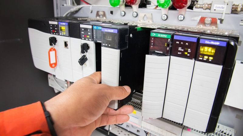
Achieving precision in PID tuning yields remarkable outcomes, such as increased system efficiency, responsiveness, and overall operational performance
Introduction
PID (Proportional-Integral-Derivative) tuning is a critical skill for engineers working with control systems across various industries. This comprehensive guide is designed to elaborate the fundamentals of PID control, and advanced tuning strategies, to equip control system designers with the knowledge and practical skills to optimize control systems effectively. Through hands-on exercises, real-world examples, and step-by-step tutorials, you'll learn how to identify and adjust PID components, implement manual and auto-tuning techniques, and troubleshoot common issues.
This guide will help designers confidently tune PID controllers for a wide range of applications, from precision motion control in robotics to temperature regulation in HVAC systems. It will provide the essential tools to master the art and science of PID tuning.
Understanding PID Controllers: The Foundation of Effective Tuning
What is PID Control?
Central to various automated systems, PID control stands for Proportional, Integral, and Derivative control. It's a type of feedback controller, that manipulates an input to a system to get the desired output. The mechanism involves monitoring the error signal, the difference between a setpoint and the measured variable. These components work harmoniously to minimize error and optimize the control variable, allowing the system to achieve and maintain the desired setpoint.
The PID controller's functionality revolves around three distinct parameters - Proportional, Integral, and Derivative. These parameters shape the controller output to drive the system towards the desired state. Each component corresponds to present, past, and future error values, providing a comprehensive control strategy.
Recommended Reading: PID Loops: A Comprehensive Guide to Understanding and Implementation
Decoding the Proportional Component: Immediate Error Correction
The proportional component in a PID controller is the primary driving force for error correction. It generates an output proportional to the current error, the difference between the setpoint and the measured process variable. In a proportional control system, the output is linearly related to the input, so the final control element has a value for each measured input value.
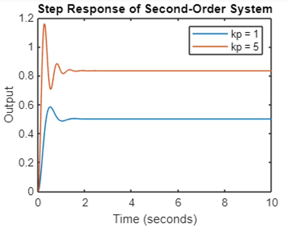
To identify and interpret the proportional component, observe the immediate response of the system to an error. A larger proportional gain results in a more aggressive response to errors.
Consider a second-order, unity feedback system that yields a transfer function:
A proportional controller Kp, is added to the system.
To calculate and adjust the proportional gain (Kp), follow these steps:
Start with a low Kp value, typically between 0.1 and 1.
Increase Kp gradually while monitoring the system response.
Observe the overshoot and settling time as Kp increases.
Find the Kp value that provides a balance between fast response and minimal overshoot.
Fine-tune Kp based on system requirements and performance criteria.
Practical Exercise:
Set up a simple temperature control system with a heating element and temperature sensor. Follow these steps to demonstrate the effect of proportional control:
Set the temperature setpoint to 50°C.
Start with Kp = 0.5 and observe the system response.
Increase Kp to 1.0, then 2.0, and note the changes in response time and overshoot.
Decrease Kp to 0.2 and observe the slower response and potential steady-state error.
Plot the temperature vs. time for each Kp value to visualize the differences.
This exercise illustrates how increasing Kp leads to a faster response but potential overshoot while decreasing Kp results in a slower response and possible steady-state error. Understanding these trade-offs is crucial for effective PID tuning.
Mastering the Integral Component: Eliminating Steady-State Error
The integral component in a PID controller accumulates the error over time, effectively eliminating steady-state error. To implement integral control, add an integral term to your control algorithm that sums the error signal over time. In comparison to proportional controllers, Integral control is slower because of their dependency on more parameters. The integral action is defined by the integral gain (Ki) or the integral time constant (Ti).
Implementing integral control:
Calculate the error signal (e) as the difference between setpoint and process variable.
Integrate the error signal over time: I = ∫e(t)dt
Multiply the integral by the integral gain: Ki*I
Add this term to your control output: u(t) = Kp * e(t) + Ki * ∫e(t)dt
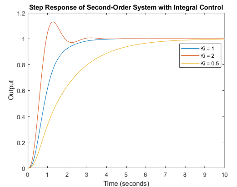
To implement integral control, consider the plant discussed earlier. This time, integral control Ki is added to the system with varying values. As the value of Ki changes, the overshoot and settling times also vary significantly.
Practical tips for setting integral time constants:
Start with a large Ti (small Ki) to avoid integral windup.
Gradually decrease Ti (increase Ki) until steady-state error is eliminated.
Monitor the system for oscillations, which indicate an overly aggressive integral action.
Use anti-windup techniques, such as integral clamping, to prevent excessive integral accumulation.
Consider the process dynamics; slower processes generally require larger Ti values.
Hands-on example:
Tuning integral component for temperature control Setup: A water heating system with a 100-liter tank, heating element, and temperature sensor. Goal: Maintain water temperature at 60°C.
Start with proportional control only (Kp = 2, Ki = 0).
Observe steady-state error (e.g., temperature stabilizes at 58°C).
Introduce integral control with Ti = 300 seconds (Ki = Kp / Ti = 0.0067).
Monitor temperature over time; it should gradually approach set point.
If convergence is too slow, decrease Ti to 200 seconds (Ki = 0.01).
Fine-tune Ti until steady-state error is eliminated without introducing oscillations.
Record the final temperature response and note the elimination of steady-state error.
By carefully adjusting the integral component, you can eliminate steady-state error while maintaining system stability. Remember that aggressive integral action can lead to overshoot and oscillations, so balance is key in achieving optimal performance.
Implementing Derivative Control
A derivative controller anticipates future errors by considering the rate of change of the error signal. Unlike P and I control derivative control is a feed-forward control that minimizes the error change. This predictive action helps to dampen oscillations and improve system stability. Implementing derivative control requires careful consideration of noise sensitivity and system dynamics.
Methodology for implementing derivative control:
Calculate the error signal (e) as the difference between setpoint and process variable.
Compute the rate of change of the error: de/dt = (e(t) - e(t-1)) / Δt
Multiply the derivative by the derivative gain: Kd * de/dt
Add this term to your control output: u(t) = Kp * e(t) + Ki * ∫e(t)dt + Kd * de/dt
The value of Kd significantly affects the system response. A higher value of Kd can make the system more sensitive to errors but may also induce instability.
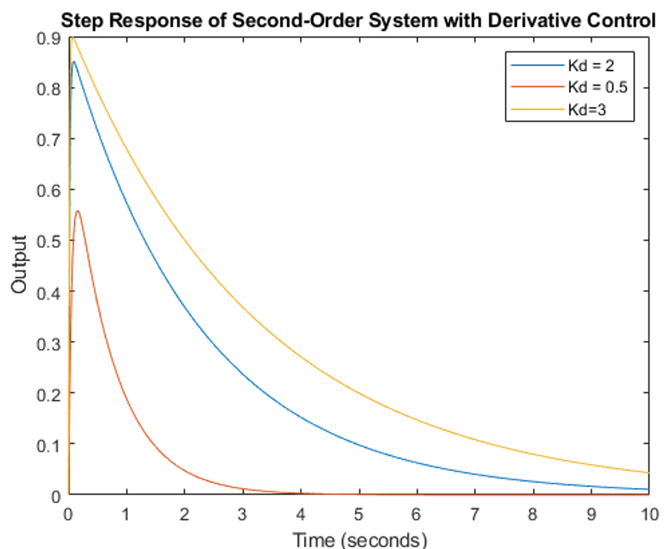
Here is a step-by-step tutorial for fine-tuning the derivative component:
Start with a stable P or PI controller.
Set the initial derivative time (Td) to 1/8 of the integral time (Ti).
Gradually increase Kd (or decrease Td) while observing system response:
Monitor overshoot reduction and settling time improvement.
Watch for increased noise in the control signal.
If noise becomes problematic, implement a low-pass filter:
Choose a filter time constant (τ) based on system dynamics.
Apply the filter to the error signal: e_filtered = (τ * e_previous + Δt * e_current) / (τ + Δt)
Fine-tune Kd to balance performance and robustness:
Increase Kd to improve transient response.
Decrease Kd if the system becomes too sensitive or noisy.
Test the system with various setpoint changes and disturbances:
Verify improved response compared to P or PI control.
Ensure stability across the entire operating range.
If the derivative kick is observed, modify the algorithm to apply derivative action only to the process variable: u(t) = Kp * e(t) + Ki * ∫e(t)dt - Kd * d(PV)/dt
Iterate steps 3-7 until optimal performance is achieved, balancing responsiveness, stability, and noise rejection.
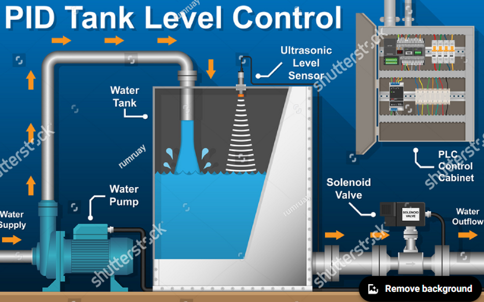
The implementation of PID controllers is one of the fundamental elements in industrial setups such as automated assembly lines, process control, temperature control, etc.
Suggested Reading: Process Control: A Comprehensive Guide to Implementation and Understanding in Industrial Systems
Essential PID Tuning Techniques: Building Your Tuning Toolkit
Mastering Manual Tuning: Developing Your Intuition
Manual PID tuning is an essential skill for control engineers, allowing for fine-tuned system performance based on observed behavior. While it requires practice and patience, manual tuning often leads to a deeper understanding of the system dynamics.
Step-by-step guide to manual PID tuning:
Set all gains to zero (Kp = 0, Ki = 0, Kd = 0).
Increase Kp until the system responds to setpoint changes with acceptable speed, but without excessive overshoot.
Increase Ki gradually to eliminate steady-state error. Watch for oscillations or instability.
If needed, introduce Kd to reduce overshoot and dampen oscillations. Be cautious, as too much derivative action can introduce noise sensitivity.
Fine-tune all parameters iteratively, making small adjustments and observing the system response.
Test the system with various setpoints and disturbances to ensure robust performance.
A practical walkthrough of the Ziegler-Nichols method:
Disable integral and derivative actions (set Ti = ∞ and Td = 0).
Increase Kp until the system exhibits sustained oscillations. This gain is the ultimate gain (Ku).
Measure the period of oscillations (Tu).
Calculate PID parameters based on Ziegler-Nichols rules:
Kp = 0.6 * Ku
Ti = 0.5 * Tu
Td = 0.125 * Tu
Convert Ti and Td to Ki and Kd:
Ki = Kp / Ti
Kd = Kp * Td
Implement these values and observe the system response.
Fine-tune parameters if necessary, using the Ziegler-Nichols values as a starting point.
How to Develop Tuning Intuition
Here are some tips for developing tuning intuition:
Start with a simplified model: Begin tuning on a simulated or simplified version of your system to build initial intuition.
Understand the impact of each term:
Increasing Kp: Faster response, potential overshoot
Increasing Ki: Eliminates steady-state error, potential oscillations
Increasing Kd: Reduces overshoot, potential noise sensitivity
Use trend analysis: Keep a log of parameter changes and corresponding system responses. Look for patterns to guide future tuning decisions.
Practice with various systems: Tune PID controllers for different types of systems (e.g., temperature control, motor speed control) to broaden your experience.
Utilize step response analysis: Observe how the system responds to step changes in setpoint. This can provide valuable insights into system behavior.
Learn from overshoot: If you encounter excessive overshoot, analyze whether it's due to high Kp or insufficient Kd.
Pay attention to rise time vs. settling time: Balance the trade-off between quick response (rise time) and stability (settling time).
Use visualization tools: Plot system responses and control signals to gain a better understanding of the system dynamics.
Leveraging Auto-Tuning Algorithms: Streamlining the Tuning Process
Auto-tuning algorithms offer a systematic approach to PID controller tuning, reducing the time and expertise required for manual tuning. These control algorithms automatically determine optimal PID parameters based on the system's dynamic response.
Implementing auto-tuning algorithms typically involves the following steps:
System Identification: Excite the system with a predetermined input signal (e.g., step or relay feedback) and record the output response.
Model Estimation: Use the input-output data to estimate a simplified model of the system dynamics.
Controller Design: Apply the chosen auto-tuning method to calculate PID parameters based on the estimated model.
Parameter Implementation: Update the PID controller with the calculated parameters.
Performance Verification: Test the system response and fine-tune if necessary.
Different auto-tuning methods offer various advantages and limitations. Here's a comparison of popular auto-tuning algorithms:
Auto-Tuning Method | Pros | Cons |
Ziegler-Nichols | Simple to implement and understand, widely used. | May result in oscillation or overshoot. |
Relay Feedback | Can identify critical gain and oscillation period effectively. | Requires a stable system, may not work for all processes. |
Internal Model Control (IMC) | Robustness to model inaccuracies. | More complex and requires accurate model of the process. |
Cohen-Coon | Good for processes with significant lag. | Not as effective for highly non-linear systems. |
Model Reference Adaptive Control (MRAC) | Adjusts automatically to changes in system dynamics. | Complex to implement and tune. |
Applying Relay Feedback Auto-Tuning to a Temperature Control System
Consider a chemical reactor where temperature control is critical. We'll use the relay feedback method to auto-tune the PID controller:
Setup: Connect the PID controller in a feedback loop with the reactor's temperature sensor and heating element.
Initiate Auto-Tuning:
Set the controller to relay feedback mode.
Define a small relay amplitude (e.g., ±5% of the control range).
Observe Oscillations:
The system will begin to oscillate as the relay switches between its high and low states.
Record the oscillation period (Tu) and amplitude (a).
Calculate PID Parameters:
Determine the ultimate gain: Ku = (4 * relay amplitude) / (π * oscillation amplitude)
Use Ziegler-Nichols rules to calculate PID parameters: Kp = 0.6 * Ku Ti = 0.5 * Tu Td = 0.125 * Tu
Implement and Verify:
Update the PID controller with the calculated parameters.
Test the system response to setpoint changes and disturbances. c. Fine-tune manually if necessary for optimal performance.
Fine-Tuning for Optimal Performance: Polishing Your Control System
Fine-tuning a PID controller is crucial for achieving optimal performance in complex control systems. This process involves making subtle adjustments to the controller parameters to improve response time, reduce overshoot, and enhance overall system stability.
Advanced tips for fine-tuning PID controllers:
Utilize frequency response analysis: Employ Bode plots or Nyquist diagrams to assess system stability margins and adjust PID parameters accordingly.
Implement anti-windup techniques: Add integral windup prevention mechanisms, such as back-calculation or conditional integration, to improve performance during saturation conditions.
Apply setpoint weighting: Modify the setpoint influence on proportional and derivative actions to reduce overshoot without sacrificing disturbance rejection.
Use derivative filtering: Implement a low-pass filter on the derivative term to reduce noise sensitivity while maintaining its beneficial effects.
Employ feedforward control: Combine feedforward action with PID control to improve disturbance rejection and setpoint tracking.
Optimize for specific performance criteria: Use advanced optimization algorithms (e.g., particle swarm optimization or genetic algorithms) to fine-tune parameters based on specific performance metrics.
Step-by-step guide to implementing gain scheduling:
Identify operating regions: Analyze the system's behavior across its entire operating range and identify distinct regions where dynamics change significantly.
Determine optimal PID parameters: For each operating region, find the optimal PID parameters using manual tuning, auto-tuning, or model-based methods.
Define scheduling variables: Choose appropriate variables (e.g., setpoint, process variable, or external conditions) that correlate with changes in system dynamics.
Create a lookup table or function: Develop a mapping between the scheduling variables and the optimal PID parameters for each operating region.
Implement interpolation: Design an interpolation mechanism to smoothly transition between parameter sets when operating between defined regions.
Integrate with the control system: Modify the PID controller to continuously update its parameters based on the current values of the scheduling variables.
Add safety checks: Implement limits on parameter variations and rate of change to ensure stable transitions.
Test and validate: Thoroughly test the gain-scheduled controller across the entire operating range and under various disturbance conditions.
A Case Study for PID Fine Tuning
A group of researchers designed a PID controller for pH neutralization process. The proposed method featured three fine-tuning methods i.e.
Marlin Method
Smith Method
Branica Method
The study concluded that the Branica tuning method is more optimal out of the three methods and is more efficient for pH neutralization in waste-water treatment, food industry, and pharmaceutical sectors.
Integrating Fuzzy Logic with PID: Enhancing Control with Expert Knowledge
Fuzzy logic integration with PID control combines the precision of traditional PID controllers with the flexibility and intuition of human expertise. This hybrid approach allows for improved performance in complex, nonlinear systems where conventional PID control may struggle.
Process of incorporating fuzzy logic into PID control:
Define Fuzzy Variables: Identify key input and output variables for the fuzzy logic controller. For PID control, typical inputs include error (e) and change in error (de/dt), while the output is the control signal adjustment.
Design Fuzzy Membership Functions: Create membership functions for each fuzzy variable. These functions map crisp input values to fuzzy sets. Common shapes include triangular, trapezoidal, and Gaussian functions. For example:
Error (e): {Negative Large, Negative Small, Zero, Positive Small, Positive Large}
Change in Error (de/dt): {Decreasing, Steady, Increasing}
Output: {Decrease Large, Decrease Small, No Change, Increase Small, Increase Large}
Establish Fuzzy Rules: Develop a rule base that captures expert knowledge about the system behavior. Rules are typically expressed as IF-THEN statements. For example:
IF error is Positive Large AND change in error is Increasing THEN output is Increase Large IF error is Zero AND change in error is Steady THEN output is No ChangeCreate the Fuzzy Inference System: Implement the fuzzy inference mechanism to evaluate the rules based on current inputs and determine the appropriate control action.
Defuzzification: Convert the fuzzy output into a crisp value that can be used to adjust the PID parameters or directly control the process. Common methods include centroid defuzzification and mean of maximum.
Exploring Model Predictive Control: Beyond Traditional PID
Model Predictive Control (MPC) is an advanced control strategy that uses a dynamic model of the process to predict future behavior and optimize control actions. Unlike PID control, MPC can handle complex, multivariable systems and incorporate constraints explicitly.
Step-by-step guide to implementing basic MPC:
Develop a process model: Create a mathematical model that accurately represents the system dynamics. This could be a state-space model, transfer function, or difference equation.
Define the cost function: Formulate an objective function that quantifies the control performance, typically including terms for setpoint tracking and control effort minimization.
Specify constraints: Identify and mathematically express any operational constraints on inputs, outputs, or states.
Choose the prediction and control horizons: Select appropriate time horizons for predicting future behavior and calculating control actions.
Implement the optimization algorithm: Use numerical optimization techniques (e.g., quadratic programming) to solve the constrained optimization problem at each time step.
Apply receding horizon principle: Implement only the first calculated control action, then repeat the optimization process at the next time step with updated measurements.
Integrating MPC with existing PID systems:
Identify the controlled variable and manipulated variable in the existing PID loop.
Develop an MPC model that includes the dynamics of the PID-controlled process.
Design the MPC cost function to prioritize smooth transitions and minimal disruption to the existing PID control.
Implement the MPC as a supervisory layer that provides setpoint adjustments to the PID controller.
Gradually increase the influence of the MPC by adjusting the weighting factors in the cost function.
Monitor system performance and fine-tune the MPC parameters as needed.
Comparative analysis of MPC and PID performance:
Consider a temperature control system for a chemical reactor:
Pros | Cons | |
PID Control |
|
|
MPC Performance |
|
|
Simulation Results: The provided image illustrates an MPC simulation for setpoint tracking. Key observations:
MPC (blue line) smoothly approaches the setpoint (red dashed line) without overshoot.
The predicted output demonstrates the MPC's ability to anticipate future system behavior.
The control action is implicitly constrained, as evidenced by the smooth approach to the setpoint.
In contrast, a PID controller might exhibit overshoot or oscillations, especially if not properly tuned. The MPC's predictive nature allows it to achieve optimal performance while respecting system constraints.
Code example for basic MPC implementation:
import numpy as np
import matplotlib.pyplot as plt


# MPC parameters
sampling_time = 0.1  # seconds
prediction_horizon = 10  # number of steps


# System dynamics (example: a simple first-order system)
setpoint = 1.0
x = 0.0  # Initial state


# MPC controller gain (tunable)
gain = 5.0


predicted_output = []


for step in range(prediction_horizon):
    error = setpoint - x
    x += gain * error * sampling_time  # Simple proportional control for system response
    predicted_output.append(x)


# Plotting results
plt.figure(figsize=(10, 5))
plt.plot(predicted_output, label='Predicted Output (MPC)', color='blue')
plt.axhline(y=setpoint, color='red', linestyle='--', label='Setpoint')
plt.title('Model Predictive Control Simulation')
plt.xlabel('Time Steps')
plt.ylabel('Output')
plt.legend()
plt.grid()
plt.show()
This simplified MPC example demonstrates the core concept of predicting future system behavior and optimizing control actions accordingly. In practice, more sophisticated optimization algorithms and constraints would be incorporated to fully leverage the capabilities of MPC.
Conclusion
PID tuning is a critical skill for control engineers across various industries. This guide has equipped you with:
Understanding of PID components and their effects on system response
Manual and auto-tuning techniques for optimal controller performance
Advanced strategies like adaptive PID, fuzzy logic integration, and model predictive control
Practical implementation skills through hands-on examples and case studies
Engineers in fields such as robotics, process control, aerospace, and automotive can significantly improve system performance by mastering these PID tuning techniques. Apply these skills to optimize control systems in your specific domain, enhancing efficiency, stability, and overall product quality.
Frequently Asked Questions
How do I choose initial PID parameters for manual tuning?
Start with a low proportional gain (Kp), zero integral (Ki), and zero derivative (Kd). Gradually increase Kp until you observe a stable oscillation, then adjust Ki and Kd to refine the response.
What should I do if my system shows persistent oscillations after tuning?
Reduce the proportional gain (Kp) slightly and increase the derivative gain (Kd) to dampen oscillations. If the problem persists, consider reducing the integral gain (Ki) or implementing an anti-windup mechanism.
How can I handle significant time delays in my control system?
For systems with large time delays, consider using a Smith Predictor or implementing a model predictive control (MPC) strategy, which can better account for delays in the control algorithm.
When should I consider switching from PID to more advanced control strategies? Consider advanced strategies like MPC or adaptive control when dealing with highly nonlinear systems, systems with multiple inputs/outputs, or when you need to explicitly handle constraints on process variables.
How often should I re-tune my PID controller in an industrial setting?
Re-tuning frequency depends on the process dynamics. For stable processes, annual re-tuning may suffice. For processes with changing dynamics (e.g., due to equipment wear), implement adaptive tuning or schedule more frequent manual re-tuning sessions.
What are some common signs that my PID controller needs tuning?
Look for excessive overshoot, slow response to setpoint changes, persistent oscillations, or steady-state errors. These symptoms often indicate suboptimal PID parameters.
References
Proportional Control Basics – Technology Transfer Services (techtransfer.com)
9.2: P, I, D, PI, PD, and PID control - Engineering LibreTexts
FUZZY PID CONTROLLERS. Introduction | by Niranjana Madathil | K. R. I. S. S | Medium
https://www.omega.co.uk/prodinfo/how-to-tune-a-pid-controller.html
Table of Contents
IntroductionUnderstanding PID Controllers: The Foundation of Effective TuningWhat is PID Control?Decoding the Proportional Component: Immediate Error CorrectionPractical Exercise: Mastering the Integral Component: Eliminating Steady-State ErrorHands-on example: Implementing Derivative ControlEssential PID Tuning Techniques: Building Your Tuning ToolkitMastering Manual Tuning: Developing Your IntuitionHow to Develop Tuning IntuitionLeveraging Auto-Tuning Algorithms: Streamlining the Tuning ProcessApplying Relay Feedback Auto-Tuning to a Temperature Control SystemFine-Tuning for Optimal Performance: Polishing Your Control SystemA Case Study for PID Fine Tuning Integrating Fuzzy Logic with PID: Enhancing Control with Expert KnowledgeExploring Model Predictive Control: Beyond Traditional PIDConclusionFrequently Asked QuestionsReferences
