Enabling Robust Automotive Communication: Ethernet ESD Protection
As data rates in automotive communication networks increase optimized ESD protection concepts become critical.

Byton
Co-authored by Andreas Hardock
Introduction
Automotive connectivity, such as telematics and infotainment, as well as autonomous driving trends are pushing demand for higher data-transfer rates within the vehicle. To meet this need vehicles have a growing number of computer-based systems, applications, and connections as well as the cabling, network interfaces, and onboard computing power to support them. Automotive ethernet is now at a stage where it can reliably reduce these electronic costs and support increasing bandwidth requirements.
While automotive ethernet usage solves some problems it also brings to light the critical importance of Electrostatic Discharge (ESD) robustness to ensure the reliable high performance of automotive communication networks. As data rates in a communication network increase ESD robustness decreases.
In simple terms, ESD is the release of static electricity when two objects come into contact. It produces a high current in a very fast event. Much like the shock you can get from a door handle after walking on particular carpets. In an automotive setting, ESD events can result in sub-micron damage to the device that can lead to device failure. This article will examine how the risk of ESD can be mitigated with an optimized ESD protection concept.
The current state of in-vehicle networks
The current makeup of today’s in-vehicle networks is a culmination of past technologies including Local Interconnect Network (LIN) and Controller Area Network (CAN) as well as CAN-FD which is gaining more importance due to flexible data rates. This presents a challenge for the industry as it aims to both reduce the number of technologies while at the same time retaining the necessary legacy technologies to reduce cost and retain reliability.
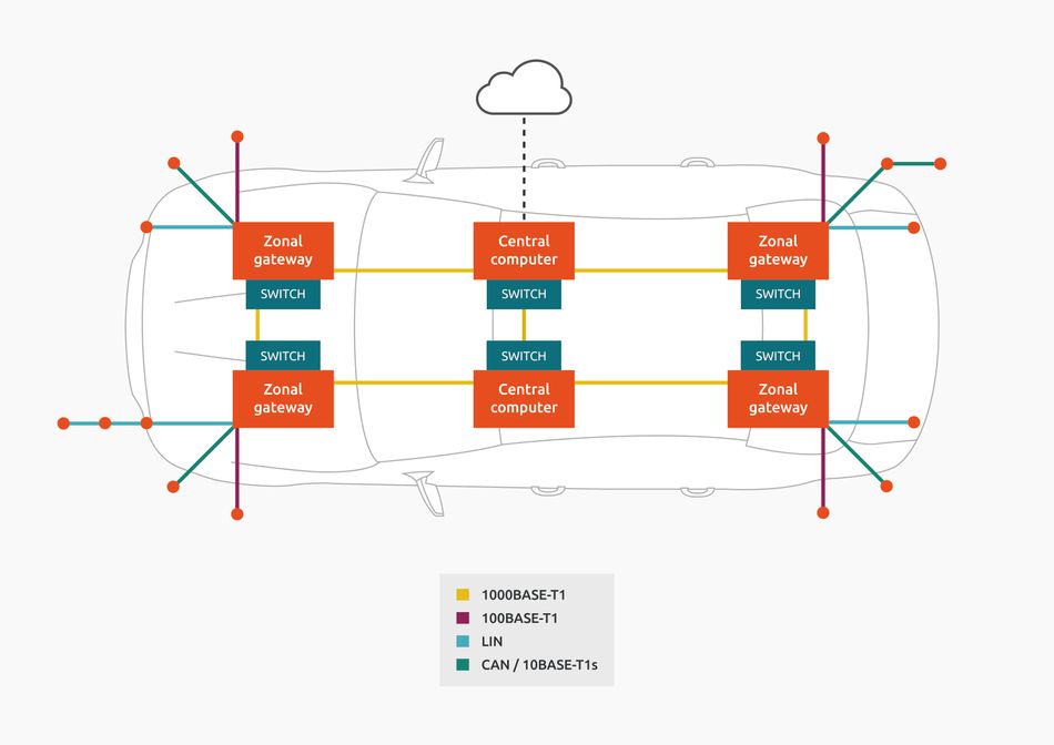
All automotive subsystems were initially connected by dedicated cables. However, as automotive systems became more complex, and the number of automotive subsystems relying on electronics increased, so did the amount of cabling required for their interconnection. The concept of fieldbuses was introduced. A fieldbus is a serial bus allowing message exchange between nodes connected to the fieldbus. Using a fieldbus, several previously dedicated cables are replaced by a serial bus interconnecting the ECUs. This decreased both the weight and cost of the automotive system. More recently, in response to the ever-increasing network demands, in-vehicle networks now use zonal architecture which aims to form a network by which any Electric Control Unit (ECU) can talk to any other.
To do so, every ECU is connected to a domain or zone controller directly via a short CAN, LIN, or 10BASE-T1s interface. The domain or zone controllers are connected using a high-speed backbone network technology such as Automotive Ethernet (IEEE automotive Ethernet standards 100BASE-T1, 1000BASE-T1, and 1000BASE-RH) which provides flexibility and determinism (see Figure 1).

Software for versatility
Software is integral to making the zonal architecture system versatile. It allows for virtual CAN/LIN networks to be implemented, so that legacy ECUs can operate as though via a CAN-/LIN-only topology. Software also means that every ECU with a dynamic Internet Protocol (IP) address can be used in plug-and-play operations as well as support features such as over-the-air updates. Secure sub-networks can also be formed based on software to ensure compliance with safety standards in safety-critical applications and to protect sensitive data.
Automotive Ethernet
Automotive Ethernet is a physical network that is used to connect components within a car using a wired network. In the past, it was previously reserved for limited to data heavy applications that CAN and FlexRay were unable to provide such as diagnostics, in-vehicle-infotainment (IVI) systems, and connecting remote sensors. However, the technology has now matured and is ready to meet the demand of fast-growing trends such as autonomous vehicles, providing the desired flexibility for zonal architecture configuration. It is also easy for engineers to implement with globally recognized standards specific to the automotive market.
Advancing specifications
The Institute of Electrical and Electronic Engineers (IEEE) recognizes three automotive Ethernet standards; 100BASE-T1,1000BASE-T1 and 1000BASE-RH that can meet automotive emissions standards and reduce cabling weight and cost in automotive networking[1]. The standard was ushered in by the work of the OPEN (One-Pair EtherNet) Alliance, a special interest group formed by major automotive OEMs and tier-one suppliers who are collaborating to push the wide-scale adoption and standardization of Ethernet-based networks and their security and reliability. The alliance was early adopters of automotive Ethernet and have been key in defining automotive ethernet standards.
ESD robustness
Automotive Ethernet Systems have to pass several environmental tests to be very robust in the field at any climate condition. One of these is the System-level ESD robustness which is a very crucial feature for any electronic system, even more so in an automotive environment where smaller ICs mean a loss of space for internal ESD protection. These smaller devices are also vulnerable as even lower voltages can damage the thinner gate oxide. The danger posed by potential system failures caused by ESD is severe - particularly in autonomous driving technologies. Both discrete ESD protection devices as well as the system design play a role. Rigorous ESD protection can be avoided or heavily mitigated with an optimized ESD protection concept. ESD protection depends on several factors beyond the robustness of individual components, including the robustness of the weakest device in the system, the properties of the protection device, the properties of other elements in the signal path, and the parasitic effects arising from the board and mounting wires.
SEED simulation methodology for product development
System-efficient ESD design (SEED) is a system-level approach to ESD simulation to develop protection components suitable for increasing demand. The concept of SEED is to consider all the parameters of ESD protection as outlined above into account in the form of an equivalent circuit or circuit-like simulation to predict system-level robustness. More detail on SEED can be found here. OPEN Alliance members use SEED methodology when developing silicon-based, OPEN Alliance-compliant ESD protection for 100 and 1000baseT1 Automotive Ethernet systems
Redesigning physical systems
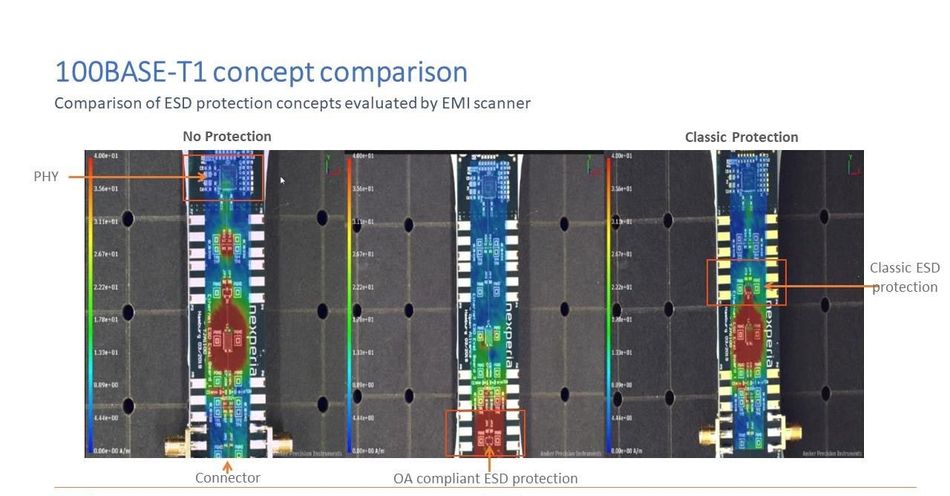
In previous Automotive Ethernet implementations, PHY (physical layer interface, referring to the transceiver) vendors were advised to put any required discrete ESD protection device between the CMC (common-mode choke) and the PHY.
Now, the ESD protection device is recommended to be placed immediately next to the connector, protecting not only the PHY but also the CMC and passives. In this position, external ESD protection is decoupled from internal protection of the PHY and protects also the DC block as well as other passive components. In the figure above there is a comparison shown between the OA approach with the ESD protection close to the connector (middle), a classic approach with the ESD protection close to the PHY (right), and without any ESD protections (left). The red color indicates a high current density. One can see that having the OA approach provides by far the lowest currents at the circuitry behind the ESD protection and especially the PHY. This means the best ESD robustness for the entire Ethernet system.
Nexperia ESD solutions
Nexperia, a leading semiconductor manufacturer and technical member of theOPEN Alliance, used the SEED methodology to replicate the ESD Discharge Current Measurement test when developing the industry’s first silicon-based, ESD protection for 100/1000BAASE-T1 automotive Ethernet systems. Silicon-based ESD protection devices offer a significantly higher performance level of protection - up to 30 kV system level robustness – than competing technologies such as varistors.
Nexperia has a wide range of discrete components for ESD protection in targeted applications:
ESD protection for in-vehicle network lines in automotive environments
OPEN Alliance 100BASE-T1 Ethernet and 1000BASE-T1 Ethernet
PESD2CANFDx series for CAN-FD bus
Key features and benefits of the first two OPEN Alliance Ethernet compliant ESD Protection devices:
PESD2ETH100-T For 100BASE-T1 Ethernet
Fully 100BASE-T1 OPEN Alliance compliant
Low capacitance <3pF
ESD protection up to 30kV (IEC 61000-4-2, contact)
1000 contact discharges with 30 kV (IEC 61000-4-2)
High trigger voltage: Vt1 = 10V min.
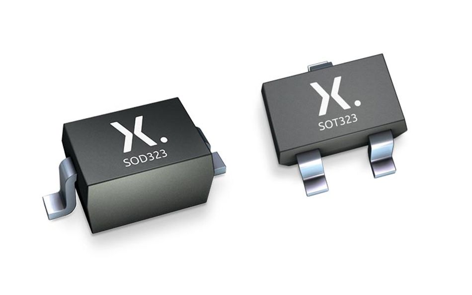
SOT23 package
AEC-Q101 qualified/automotive grade
PESD2ETH1G-T For 100/1000BASE-T1 Ethernet
Fully 100/1000BASE-T1 OPEN Alliance compliant
Low capacitance <2pF
ESD protection up to 30kV (IEC 61000-4-2, contact)
1000 contact discharges with 15kV (IEC 61000-4-2)
High trigger voltage: Vt1 = 100V min.
SOT23 package
AEC-Q101 qualified/automotive grade
Nexperia also has solutions for other relevant technologies within the network including: PESD2CANFDx for CAN-FD and PESxIVNx Series for LIN and CAN. More on these solutions can be found here.
Essential elements for ESD design
Nexperia’s ESD products can help minimize the risk of ESD damage while their research, knowledge, and design guides support the engineering community in protecting applications and products against ESD issues. To help designers navigate ESD protection, Nexperia has developed a set of ‘golden rules’ for ESD design.
Place the device as close to the input terminal or connector as possible.
Provide a solid ground connection for the device
Keep parallel signal paths to a minimum.
Avoid running protected conductors in parallel with unprotected conductors.
Minimize all Printed-Circuit-Board (PCB) conductive loops including power and ground loops.
Minimize the length of the transient return path to ground.
Avoid using shared transient return paths to a common ground point.
Use ground planes whenever possible. For multilayer PCBs, use enough ground vias.
Conclusion
The increasing demands for higher bandwidth and low-latency communication in automotive are driven by the exciting increase in drive-assist technology, infotainment, connectivity, and autonomous driving. Automotive ethernet can reliably support these increasing bandwidth requirements but its adoption must be tied with optimized ESD protection concepts. The challenges of automotive communication can be met with new ESD protection concepts that deliver high system-level robustness, good signal integrity, and PCB design flexibility.
About the sponsor: Nexperia
Nexperia is the expert in high-volume production of discrete and MOSFET components and analog & logic ICs that meet the stringent standards set by the Automotive industry. With an absolute focus on efficiency, Nexperia consistently produces the essential semiconductors required by every electronic design in the world: more than 90 billion annually. Products that are benchmarks in efficiency - in process, size, power, and performance - with industry-leading small packages that save valuable energy and space.
With decades of experience, supplying to the world’s biggest companies, Nexperia has over 11,000 employees across Asia, Europe, and the U.S., offering global support. The company has an extensive IP portfolio and is certified to IATF 16949, ISO 9001, ISO 14001, and OHSAS 18001.
References
https://standards.ieee.org/standard/802_3bw-2015.html


