Importance of Parameters for Metal 3D printing
Metal 3D printing requires precise control over a variety of parameters to achieve high-quality parts. Whether you're printing aerospace components, medical devices, or complex machinery, understanding the core settings that influence the outcome is crucial. Lets talk about the most important ones.
25 Oct, 2024. 3 minutes read
While the 3D printer itself plays a significant role, the parameters used during the printing process are equally important. This article dives into four critical factors: layer thickness, laser power, scan speed, and hatch distance.
Let’s break them down, how they work, and why they matter.
1. Layer Thickness: The Foundation of Detail and Strength
Layer thickness refers to the height of each individual layer of material that is deposited during the printing process. In metal 3D printing, this is typically measured in microns (µm). A smaller layer thickness results in finer detail and smoother surfaces but increases the printing time. Conversely, a larger layer thickness speeds up the process but may result in reduced resolution and potentially weaker bonding between layers.
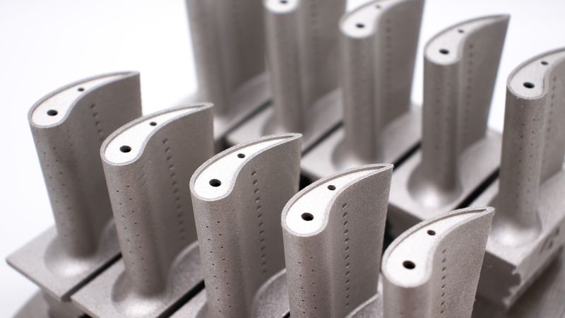
Imagine you are printing a small, intricate part, like a turbine blade. In this case, precision and surface quality are key, so you would use a smaller layer thickness, maybe around 20µm. This ensures that the part’s fine edges and smooth surfaces are accurately captured. However, if you're printing a larger, less detailed object like a simple block for structural support, you might choose a larger layer thickness, such as 50µm, to speed up the process without sacrificing too much in terms of quality.
2. Laser Power: The Fuel Behind the Process
Laser power determines how much energy is used to melt and fuse the metal powder in each layer. The laser essentially traces the shape of the part, melting the powder in specific areas. The higher the laser power, the more energy is applied to the material.
However, laser power must be carefully balanced. Too much power can cause problems, such as excessive heat, which can lead to defects like warping or "mold formation" (unwanted structures due to overheating). On the other hand, too little power may result in incomplete melting, which creates weak or porous parts that can easily break under stress.
Consider printing a dense, durable part, like a component that will be used in an engine. You’d want to use enough laser power to ensure the metal fuses solidly. But for lightweight parts, where speed is prioritized, you might opt for a lower power setting, ensuring sufficient bonding while avoiding unnecessary energy use and minimizing defects.
3. Scan Speed: The Dance of Precision and Efficiency
Scan speed refers to how quickly the laser moves across the powder bed during printing. Like the other parameters, scan speed must be finely tuned for different materials and designs. Faster scan speeds lead to quicker production, but if the laser moves too fast, it might not deposit enough energy into the material, resulting in poor bonding. If the scan speed is too slow, it can lead to excessive energy deposition, which can cause defects similar to those from high laser power, such as warping.
For example, if you are working with a highly conductive material like aluminum, which requires more energy to fuse properly, a slower scan speed may be beneficial. This allows the laser to apply enough energy to melt the material fully. In contrast, for materials that require less energy, like titanium, you can afford to increase the scan speed, reducing production time without compromising quality.
4. Hatch Distance: Bridging the Gaps
Hatch distance is the distance between adjacent scan lines as the laser moves across the powder bed. Picture the process like mowing a lawn. The laser creates paths or "lanes" as it melts the powder, and the hatch distance controls how much overlap there is between these lanes. Too large a hatch distance can leave un-melted gaps, reducing the density and strength of the part. Too small a hatch distance leads to excessive overlap, which can cause excessive heat buildup, resulting in defects similar to those caused by too much laser power or slow scan speed.
Finding the right hatch distance is a balancing act. For parts requiring high density and mechanical strength, like those used in critical aerospace applications, reducing the hatch distance ensures consistent layer bonding and part integrity. But for less critical parts where speed and cost-efficiency are more important, increasing the hatch distance can significantly cut down on build time and material consumption.
The Art of Balancing Parameters
These four parameters—layer thickness, laser power, scan speed, and hatch distance—don’t exist in isolation. They interact with each other, meaning that changes to one parameter can affect the others. For example, increasing the laser power might allow for a faster scan speed or a larger hatch distance, but it could also increase the risk of defects if not balanced properly.
Achieving the right combination of settings depends heavily on the material being used and the specific goals of the project. For example, a manufacturer aiming for high-density parts may focus on optimizing hatch distance and layer thickness to reduce voids. Conversely, someone seeking faster production times might prioritize scan speed and layer thickness, adjusting laser power and hatch distance accordingly.