Metal Core PCB (MCPCB): Revolutionizing Thermal Management in Electronics
This article delves into the technology behind Metal core PCBs (MCPCBs), recent advancements, practical engineering applications, and the challenges faced in their implementation.

25 Jun, 2024. 17 minutes read
Metal Core PCB (MCPCB)
Introduction
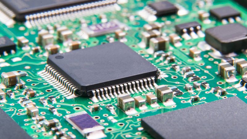
The miniaturization and ever-increasing power demands of modern electronics create a significant challenge: thermal management. Traditional printed circuit boards (PCBs) often struggle to dissipate heat effectively, leading to component overheating and potential system failure. Metal core PCBs (MCPCBs) offer a revolutionary solution!
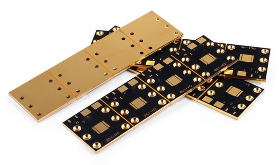
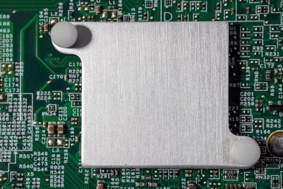
Metal Core PCBs are a specialized type of PCB that integrates a core layer of high thermal conductivity metal, typically aluminum or copper. This core acts as a highly efficient heat sink, drawing heat away from heat-generating components on the board. This innovation is crucial in fields where efficient heat management is paramount, such as in LED lighting systems, automotive electronics, and renewable energy technologies. Compared to traditional PCBs, Metal Core PCBs enable the use of higher-power components in a more compact design, pushing the boundaries of electronic performance.
The Basics of Metal Core PCBs
What Makes Up an MCPCB?
In high-power electronic applications, managing heat is crucial to ensure the reliability and longevity of components. Metal Core Printed Circuit Boards were developed to address this critical need for enhanced thermal management. By incorporating a metal core, MCPCBs provide superior heat dissipation compared to traditional PCBs, which rely solely on dielectric materials for thermal conductivity.
The metal core acts as the foundation of an MCPCB. Aluminum, widely used for its balance of cost and thermal conductivity, helps to quickly transfer heat away from vital components. [1] Copper, though more expensive, offers even higher thermal conductivity, making it ideal for applications demanding exceptional thermal performance. These metals play a pivotal role in maintaining the stability and efficiency of electronic systems under thermal stress.
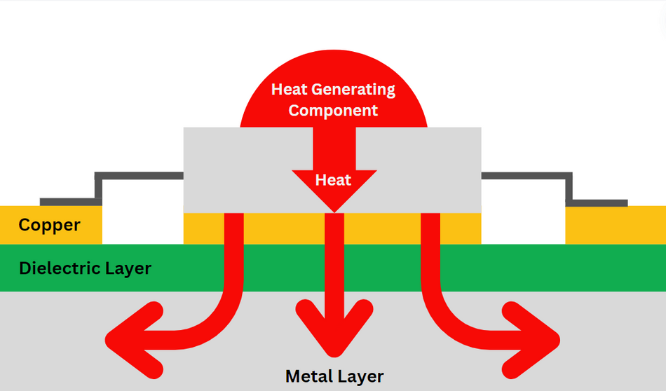
A key element of MCPCBs is the dielectric layer, which electrically insulates the metal core from the copper circuit layer while facilitating heat transfer. This layer is typically made from materials such as epoxy or ceramic-filled polymers. These materials are selected for their ability to provide a thermal conductivity range of 0.1-0.5 W/m·K, significantly better than the dielectric layers in standard PCBs. This balance of electrical insulation and thermal conduction is essential for the effective functioning of MCPCBs.
The copper circuit layer is etched to form the necessary electrical pathways for the device. This layer, similar to that in conventional PCBs, varies in thickness based on current-carrying requirements, typically ranging from 1 oz/ft² to 2 oz/ft². The copper layer, combined with the metal core and dielectric layer, enables efficient thermal management and robust electrical performance.
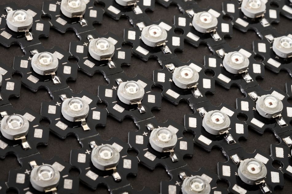
Practical applications of MCPCBs underscore their importance. For instance, in LED lighting, the ability of MCPCBs to dissipate heat effectively directly impacts the brightness and lifespan of the LEDs. In automotive electronics, where components are subject to high temperatures and demanding conditions, MCPCBs ensure reliability and performance. Renewable energy systems also benefit from MCPCBs, as they enhance the efficiency and durability of power inverters and other critical components.
By integrating these three layers, each optimized for specific thermal and electrical properties — MCPCBs offer a comprehensive solution for managing the heat generated by high-power electronic components. PCB materials hold prime importance, as they refer to all the materials used in PCB construction, including IMS (Insulated Metal Substrate), insulation layer, copper foil, and dielectric materials. MCPCBs enhance performance, reliability, and lifespan, making them crucial in modern electronic design.
Types of MCPCBs
There are several ways to classify MCPCBs (Metal Core PCBs) depending on the configuration of the metal core and circuit layers. MCPCBs are classified into five basic types:
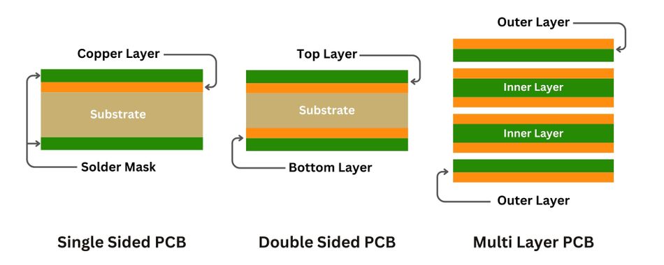
1. Single Layer MCPCB
This is the simplest type, featuring a single conductive layer on one side of the metal core. It's often used in LED lighting applications where heat dissipation is crucial for a single layer of LEDs. MCPCB offers good thermal performance and is used in various applications such as audio devices, relays, LED lighting, sensor products, and packaging equipment.
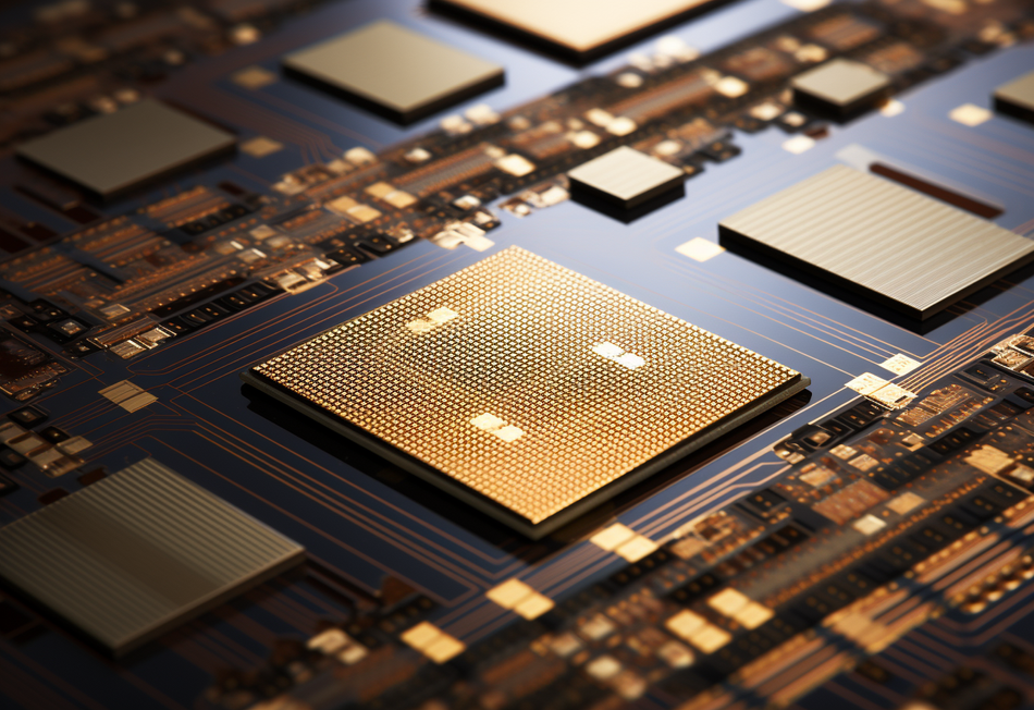
2. COB (Chip-on-Board) MCPCB
Similar to a single-layer MCPCB, it has one conductive layer but the components are mounted directly on the metal core for even better heat transfer. In COB MCPCBs, microchips directly contact the metal core for superior heat dissipation. This eliminates the dielectric layer present in traditional MCPCBs, resulting in significantly higher thermal conductivity. COB MCPCBs are ideal for applications requiring exceptional thermal management, including electronic lighting fixtures, high-power LEDs, power supplies, LED backlighting, automotive applications, and more.
3. Double Layer MCPCB
This type has two copper conductive layers on the same side of a metal core, typically aluminum. Double-layer MCPCBs offer improved functionality over single-layer boards and are used in office automation equipment, power modules, audio equipment, power controllers in automobiles, and communication electronics.
4. Double-Sided MCPCB
Similar to double-layer MCPCBs, double-sided MCPCBs have two copper conductor layers but with the metal core sandwiched between them. This allows for components to be mounted on both sides of the board. Applications include line reactors, industrial control systems, regulators, power supplies, converters, HVAC systems, hard disk drives, automotive dashboards, and transportation systems.
5. Multi-Layer MCPCB
The most complex type, multi-layer MCPCBs incorporate multiple conductive layers separated by thermally conductive dielectric material. These boards offer the highest level of functionality but also require the most advanced and expensive manufacturing techniques. Multi-layer MCPCBs are used in demanding applications such as file servers, weather analysis devices, particle accelerators, and nuclear detection systems. They are also used in medical equipment (heart monitors), fiber optic sensors, satellites, and signal transmission systems.
Aluminum PCBs offer good dimensional stability due to the higher rigidity of aluminum, which is important for precise circuit function. Aluminum substrate is used as the metal base due to its excellent thermal conductivity. Some MCPCBs can be designed for high-frequency applications by using specific materials and layouts that minimize signal integrity issues.
By understanding the different MCPCB types and their strengths, engineers can select the most suitable option for their specific application, ensuring optimal thermal management, performance, and reliability in their electronic devices.
Key Differences Between MCPCBs and Standard PCBs
In high-power and high-heat electronic applications, effective thermal management is crucial to ensure system reliability and longevity. Metal Core PCBs (MCPCBs) and standard PCBs differ significantly in their ability to manage heat, mechanical stress, and electrical performance, making MCPCBs increasingly popular in demanding environments.
Thermal Conductivity:
Standard PCB: The thermal conductivity of traditional FR4 materials is much lower, generally in the range of 0.2-0.3 W/m·K. This limited capability can lead to inefficient heat management, posing risks to the components’ performance and lifespan. [2]
MCPCBs: By integrating a metal core, MCPCBs dramatically improve thermal conductivity. Aluminum cores typically offer a thermal conductivity of around 237 W/m·K, while copper cores can reach approximately 398 W/m·K. This allows for efficient heat dissipation, preventing overheating and ensuring stable operation.
Core Material:
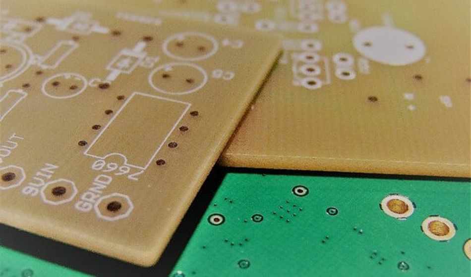
Standard PCB: The core of a standard PCB is typically made from a flame-retardant laminate material like FR4. While FR4 offers good mechanical properties and is cost-effective, it has low thermal conductivity, meaning it struggles to dissipate heat effectively.
MCPCB: The core of an MCPCB is a layer of high thermal conductivity metal, most commonly aluminum or copper. These metals excel at transferring heat away from heat-generating components.
Component Placement:
Standard PCB: Standard PCBs can accommodate both through-hole components (THT) and surface-mount technology (SMT) components. THT components require drilling holes through the PCB to connect them electrically.
MCPCB: Due to the presence of the metal core, drilling plated through-holes (vias) in single-layer MCPCBs is generally not possible. Therefore, MCPCBs primarily rely on SMD components, which are soldered directly onto the board's surface. However, Multi-layer MCPCBs with a metal core sandwiched between dielectric layers can incorporate vias for internal connections.
Electrical Performance:
Standard PCB: In Standard PCBs, higher operating temperatures can adversely affect electrical performance, leading to potential instability and reduced component lifespan.
MCPCBs: The efficient thermal management provided by MCPCBs indirectly enhances electrical performance. By maintaining optimal temperatures, MCPCBs help ensure the stability and longevity of electronic circuits, which is critical in precision and high-performance applications.
The key differences between MCPCBs and standard PCBs can be summarized in the following table:
| Feature | Standard PCB | MCPCB |
| Core Material | Organic material (FR4) | Metal (Aluminum or Copper) |
| Thermal Conductivity | Low (0.1 - 0.3 W/mK) | High (1.0 - 3.0 W/mK) |
| Heat Dissipation | Convection, Radiation | Metal Core for efficient heat transfer |
| Component Placement | Double-sided (with vias) | Single or Double-sided (limited via usage) |
| Machining | Standard Techniques | Diamond-coated tools for metal core cutting |
| Applications | Low-power Electronics | High-power Electronics, LED Lighting, Power Converters |
By addressing critical aspects of thermal management, mechanical strength, and electrical performance, MCPCBs provide a comprehensive solution for high-power electronic applications. This makes them a preferred choice over traditional FR4 PCBs in various demanding scenarios.
Recommended Reading: Types of Printed Circuit Boards: A Comprehensive Guide
Recent Technological Advancements in MCPCBs
Innovations in Material Science
Advancements in material science have significantly improved the performance and capabilities of Metal PCBs. These innovations primarily focus on enhancing the materials used for the metal core and dielectric layers, which are crucial for the overall thermal and electrical performance of the PCB.

One of the significant advancements is the development of high-performance metal cores. Recent research has led to the creation of alloyed metal cores that combine the benefits of multiple metals, providing enhanced thermal properties and mechanical strength. These alloys can achieve thermal conductivities higher than traditional metals while maintaining structural integrity under thermal stress.
Metal Matrix Composites (MMCs) combine a metal matrix with ceramic or carbon fiber reinforcements. [3] MMCs offer exceptional thermal conductivity while maintaining structural integrity. They hold promise for next-generation MCPCBs with even higher thermal performance. Similarly, Diamond, the ultimate heat conductor, is being explored for use in MCPCB substrates. While challenges in cost-effective production remain, diamond substrates could revolutionize thermal management in high-performance electronics.
Innovations in dielectric materials have also played a pivotal role in advancing MCPCB technology. Traditional dielectric layers, such as epoxy or ceramic-filled polymers, offer a thermal conductivity range of 1-3 W/m·K. However, newer materials have been developed to provide significantly better thermal and electrical performance. For example, advanced ceramic-filled polymers can now achieve thermal conductivities up to 5 W/m·K while maintaining excellent electrical insulation properties. This advancement allows for thinner dielectric layers, further reducing thermal resistance and improving overall MCPCB performance.
New composites and coatings have been introduced to further boost the thermal and electrical characteristics of MCPCBs. For instance, the use of nanocomposites incorporating materials like graphene or carbon nanotubes has shown promising results. These nanocomposites can significantly increase thermal conductivity and mechanical strength without adding substantial weight. Graphene-enhanced coatings, for example, can provide thermal conductivities exceeding 500 W/m·K, making them ideal for high-performance applications where heat dissipation is paramount.
Additionally, the development of hybrid dielectric materials that combine organic and inorganic components has resulted in dielectric layers with superior thermal and electrical properties. Polymer Matrices form the base of the hybrid dielectric, offering good electrical insulation properties. Common examples include epoxy or polyimide resins. Thermally Conductive Fillers are typically ceramic particles or metallic microfibers embedded within the polymer matrix. They significantly improve the thermal conductivity of the overall dielectric material, allowing for better heat dissipation.
This ongoing progress in material science continues to push the boundaries of what MCPCBs can achieve. This makes them indispensable in fields such as automotive electronics, LED lighting, and renewable energy systems.
Enhanced Manufacturing Techniques
Advancements in manufacturing processes have played a crucial role in enhancing the precision, efficiency, and cost-effectiveness of producing Metal plate PCBs. These cutting-edge techniques ensure that MCPCBs meet the stringent requirements of modern electronic applications.
One such technique is Laser Direct Structuring (LDS). LDS is a state-of-the-art method that allows for the precise creation of complex circuit patterns directly onto the surface of MCPCBs. This process involves the use of a laser to define the circuitry on a specially coated base material. The laser activates the coating, enabling the subsequent metallization steps to form conductive traces. The benefits of LDS include:
High Precision: LDS allows for the creation of extremely fine and accurate circuit patterns, essential for miniaturized and high-density electronic designs.
Flexibility: The process is highly adaptable, allowing for quick modifications and customization of circuit designs without the need for new tooling.
Reduced Production Costs: By eliminating the need for multiple production steps and tooling changes, LDS can significantly lower manufacturing costs.
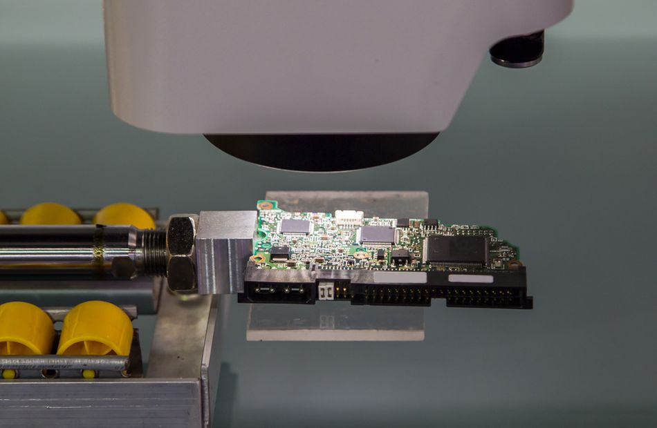
Another key innovation is the use of automated optical inspection (AOI) and automated X-ray inspection (AXI) in the manufacturing process. These techniques improve the quality and reliability of MCPCBs by ensuring:
Defect Detection: AOI and AXI systems can identify defects such as misalignments, voids, and cracks that are not easily visible, ensuring high-quality production standards.
Process Efficiency: Automated inspections reduce the time and labor required for manual checks, speeding up the production process and enhancing throughput.
Consistency: These systems provide consistent inspection results, reducing the likelihood of human error and ensuring uniform quality across all produced PCBs.
In addition to LDS and automated inspections, advanced lamination techniques have also been developed to improve the performance of MCPCBs. These techniques include:
Vacuum Lamination: This process reduces the presence of air bubbles and voids within the dielectric layer, enhancing thermal and electrical performance.
High-Pressure Lamination: Applying higher pressures during lamination ensures better adhesion between layers, increasing the mechanical strength and reliability of the PCB.
By integrating these advanced manufacturing techniques, the production of MCPCBs has become more efficient and precise. These innovations ensure that MCPCBs can meet the high demands of modern electronic applications, providing superior performance and reliability.
Recommended Reading: PCB Manufacturing Process: A Comprehensive Guide to Understanding and Mastering the Techniques
Real-World Applications of MCPCBs in Engineering
Automotive Industry
In the automotive industry, effective thermal management is crucial due to the high power demands and harsh operating conditions. Metal Core PCBs (MCPCBs) have become an essential component in automotive electronics, offering superior heat dissipation and reliability. Here are some specific applications:
LED Headlights:
Thermal Loads: LED headlights generate significant heat, which can affect their brightness and lifespan. MCPCBs efficiently dissipate this heat, maintaining optimal performance.
Electrical Specifications: Typically, automotive LED systems operate at 12V or 24V with power ratings ranging from 20W to 100W. [4] MCPCBs ensure stable operation by managing thermal loads effectively.
Power Converters:
Thermal Management: Power converters in electric vehicles (EVs) and hybrid vehicles require efficient thermal management to handle high power levels and prevent overheating. MCPCBs provide the necessary heat dissipation to maintain converter efficiency.
Technical Details: These converters often deal with power levels up to 150 kW, necessitating robust thermal solutions. MCPCBs help in managing the heat generated during power conversion processes.
Sensor Modules:
Heat Dissipation: Automotive sensors, including those used for engine control and safety systems, generate heat during operation. MCPCBs aid in dissipating this heat, ensuring accurate sensor performance.
Electrical Specifications: Sensor modules typically operate at lower voltages (5V to 12V), but require precise thermal management to prevent thermal drift and ensure reliability.
Thermal PCBS are fundamentally designed for superior thermal performance, making them ideal for applications involving high-power components and heat dissipation needs, like as Motor Control. By incorporating MCPCBs into these automotive applications, manufacturers can ensure enhanced performance, reliability, and longevity of electronic components under demanding conditions.
Renewable Energy Systems
In renewable energy systems, efficient thermal management is crucial for optimizing performance and reliability. Metal Core PCBs (MCPCBs) play a significant role in enhancing the efficiency of components used in solar power inverters and wind turbine electronics. These systems operate under high thermal loads, and effective heat dissipation is essential to maintain their functionality and longevity.
Solar Power Inverters:
Thermal Management: Solar power inverters convert the direct current (DC) generated by solar panels into alternating current (AC) for use in the grid. This process generates substantial heat, which can impair the inverter’s performance and lifespan. MCPCBs can be used in photovoltaic (solar) panels to efficiently dissipate heat generated during electricity production.
Performance Improvements: By using MCPCBs, solar power inverters can operate at higher efficiency levels. For instance, inverters with MCPCBs can achieve efficiency rates exceeding 98%, compared to lower efficiencies in systems using traditional PCBs. This improvement translates to more effective energy conversion and reduced thermal stress on components. Additionally, the enhanced thermal management provided by MCPCBs allows for more compact inverter designs, saving space and reducing material costs.
Wind Turbine Electronics:
Heat Dissipation: Wind turbines generate significant amounts of heat in their electronic control systems and power converters. Effective heat dissipation is essential to maintain system stability and prevent overheating. MCPCBs provide the necessary thermal management to ensure reliable operation under varying environmental conditions.
Technical Enhancements: Incorporating MCPCBs in wind turbine electronics improves thermal management, allowing for higher power densities and more compact designs. For example, power converters using MCPCBs can handle power ratings up to 500 kW, with improved thermal performance ensuring longevity and reliability. The efficient heat dissipation provided by MCPCBs also helps in maintaining the optimal performance of critical components. This includes pitch control systems and power electronics modules, vital for the safe and efficient operation of wind turbines.
Understanding the role of MCPCBs in these applications highlights their importance in the renewable energy sector. By integrating advanced thermal management solutions, MCPCBs contribute to the overall efficiency and reliability of renewable energy systems. This also contributes to the broader goal of sustainable energy production by maximizing the energy yield and reducing maintenance requirements.
Recommended Reading: Mastering QFN Packages: A Complete Guide to Compact and High-Performance Electronics Encapsulation
Overcoming Challenges with MCPCBs
Thermal Management and Heat Dissipation
Effective thermal management is essential for the reliable operation of Metal Core PCBs (MCPCBs). Despite their enhanced thermal conductivity, MCPCBs can face several thermal management issues that must be addressed to ensure optimal performance.
In high-power electronic applications, managing heat is crucial to prevent damage and maintain system reliability. Poor thermal management can lead to a variety of problems such as component degradation, reduced performance, and even complete system failure. Understanding and addressing common thermal issues is, therefore, vital.
Common Thermal Management Issues
Hot Spots: Localized areas of high temperature can occur due to uneven heat distribution. These hot spots can lead to component failure or reduced lifespan. They are often caused by the concentration of high-power components in a small area without adequate heat dissipation paths.
Thermal Expansion: Different materials in MCPCBs can expand at different rates when heated, potentially causing mechanical stress and damage. This mismatch in thermal expansion coefficients between materials can lead to delamination or cracking.
Thermal Cycling: Repeated heating and cooling cycles can degrade materials over time, affecting the structural integrity and performance of the MCPCB. This is especially problematic in applications with frequent power cycling or varying environmental conditions.
Technical Guidelines for Thermal Management:
Calculating Thermal Resistance
Thermal resistance (Rθ) is a key parameter in assessing a material's ability to conduct heat. It is defined as the temperature difference across a material per unit of power dissipated. The formula is stated as:

Where, ΔT is the Temperature difference (°C), while P is the Power dissipation (W).
Lower thermal resistance indicates better heat conduction. Materials with lower Rθ values are preferred for high-power applications.
Optimizing Heat Dissipation
- Material Selection: Choose materials with high thermal conductivity for both the metal core and dielectric layers. For instance, aluminum and copper are excellent choices for the metal core due to their high thermal conductivities.
- Heat Sinks and Thermal Vias: Incorporate heat sinks and thermal vias into the design to enhance heat dissipation. Thermal vias provide a path for heat to travel from the surface of the PCB to the heat sink or metal core.
- Layer Stack-Up: Optimize the layer stack-up to facilitate better heat flow. Placing high-power components close to the metal core can reduce thermal resistance and improve heat dissipation.
Design Considerations
- Component Placement: Strategically place components to minimize thermal interaction and spread heat evenly across the PCB. High-power components should be placed in areas with optimal heat dissipation paths.
- Thermal Interface Materials (TIMs): Use TIMs between components and heat sinks to improve thermal conduction. TIMs fill microscopic air gaps and provide a more efficient thermal path. [5]
- Thermal Analysis: Perform thermal simulations and analysis during the design phase to identify potential thermal issues and optimize the design for better thermal management.
Practical examples illustrate the importance of these guidelines. In power electronics, efficient thermal management ensures that power modules operate within safe temperature ranges. Similarly, in LED lighting, proper heat dissipation prevents brightness degradation and prolongs the life of the LEDs.
By following these guidelines and leveraging advanced materials and design techniques, engineers can effectively manage thermal challenges in MCPCBs, ensuring their reliable operation in high-power electronic applications.
Mechanical and Electrical Integrity
Ensuring the mechanical and electrical integrity of Metal Core PCBs (MCPCBs) is critical for their performance and reliability in demanding applications. These PCBs face several challenges, such as thermal expansion and electrical isolation, that must be addressed through careful design and material selection.
Mechanical Challenges
Thermal Expansion: Different materials in MCPCBs expand at different rates when subjected to temperature changes, which can cause mechanical stress and potential failure. For instance, the metal core and the dielectric layer have distinct coefficients of thermal expansion (CTE). This mismatch can lead to delamination or cracking if not properly managed.
Material Stress Limits: The materials used in MCPCBs must withstand the mechanical stresses induced by thermal expansion and contraction. Metals like aluminum and copper, while excellent for heat dissipation, must be chosen and treated to handle these stresses without deforming or cracking.
Design Considerations for Mechanical Integrity
CTE Matching: Select materials with compatible CTEs to minimize stress. For example, using a dielectric material with a CTE close to that of the metal material can reduce the risk of mechanical failure.
Thermal Reliefs: Incorporate thermal reliefs in the PCB design to manage the expansion and contraction stresses. These can include strategic placement of slots or cutouts that allow the material to expand without causing damage.
Electrical Challenges
Electrical Isolation: Maintaining electrical isolation between the conductive layers and the metal core is crucial. Any breach in isolation can lead to short circuits and potential system failure.
Thermal Cycling Effects: Repeated heating and cooling cycles can degrade the dielectric material, affecting its insulating properties. This is especially critical in applications with frequent power cycling or varying environmental conditions.
Design Considerations for Electrical Integrity
High-Quality Dielectrics: Use high-quality dielectric materials with excellent insulating properties and thermal stability. Materials like ceramic-filled polymers can offer both good thermal conductivity and electrical isolation.
Thickness Optimization: Optimize the thickness of the dielectric layer to ensure sufficient electrical isolation while maintaining effective heat dissipation. Thicker dielectric layers provide better insulation but can impede heat transfer.
Techniques for Enhancing Mechanical and Electrical Integrity
Thermal Cycling Testing: Perform rigorous thermal cycling tests during the design phase to identify potential issues with thermal expansion and material degradation. This testing helps in fine-tuning the material selection and design parameters.
Advanced Coatings: Apply advanced coatings to the dielectric layer to enhance its thermal and electrical properties. For example, using coatings that improve thermal conductivity without compromising electrical isolation can provide significant benefits.
Component Placement: Strategically place components to minimize thermal and electrical stress. High-power components should be positioned in areas with optimal heat dissipation paths, and sensitive components should be placed away from potential sources of electrical interference.
Understanding and addressing these challenges through thoughtful design and material selection ensures that MCPCBs can operate reliably in high-power, high-stress environments. This enhances their longevity and performance, making them a robust choice for a wide range of demanding applications.
Recommended Reading: Unfolding the Future: The Evolution and Impact of Printed Electronics
Conclusion
Throughout this article, we have explored the fundamental concepts, technological advancements, practical applications, and challenges associated with Metal Core PCBs (MCPCBs). These innovative PCBs offer superior thermal management, enhanced mechanical strength, and improved electrical performance, making them a critical component in modern engineering. MCPCBs are indispensable in high-power applications, such as automotive electronics, LED lighting, and renewable energy systems, where effective heat dissipation is paramount. As advancements in MCPCB technology continue, they will play an increasingly vital role in pushing the boundaries of electronic design and performance. Engineers and technologists are encouraged to stay abreast of these developments and consider the potential of MCPCBs in their projects.
Frequently Asked Questions
Q. What are the primary benefits of using MCPCBs over traditional PCBs?
A. MCPCBs offer several advantages over traditional PCBs, primarily in thermal management, durability, and performance. Their metal core provides superior heat dissipation, which is crucial for high-power applications. This efficient thermal management helps prevent overheating, extending the lifespan of circuit board components and enhancing overall reliability.
Q. Can MCPCBs be used in all types of electronic devices?
A. MCPCBs are highly suitable for a wide range of electronic applications, especially those requiring efficient heat dissipation. They are commonly used in high-power LED lighting, automotive electronics, and power electronics. However, they may not be necessary for low-power applications where thermal management is not a critical concern. The primary limitation is their higher cost compared to traditional PCBs, which may not be justified for applications with minimal thermal demands.
Q. How do advancements in MCPCB technology impact manufacturing costs?
A. MCPCB technology advancements impact manufacturing costs. Initial adoption of newer technologies may involve higher costs, but improved performance and reliability offset these costs. Efficient thermal management materials reduce the need for additional cooling, lowering overall system costs. Innovations in manufacturing techniques enhance production efficiency and reduce waste, further mitigating costs. Long-term cost savings from enhanced performance often outweigh the initial investment.
References
[1] NIC. Thermal Conductivity of Aluminum Alloys—A Review - PMC [Cited 2024 June 24] Available at: Link
[2] JHDPCB. High Quality Metal Core PCB Manufacturing [Cited 2024 June 24] Available at: Link
[3] Princeton University. Metal Matrix Composites [Cited 2024 June 24] Available at: Link
[4] IEEE. LED Systems Applications and LED Driver Topologies [Cited 2024 June 24] Available at: Link
[5] CUI DEVICES. The Importance of Thermal Interface Materials [Cited 2024 June 24] Available at: Link
Table of Contents
IntroductionThe Basics of Metal Core PCBsWhat Makes Up an MCPCB?Types of MCPCBs Key Differences Between MCPCBs and Standard PCBsRecent Technological Advancements in MCPCBsInnovations in Material ScienceEnhanced Manufacturing TechniquesReal-World Applications of MCPCBs in EngineeringAutomotive IndustryRenewable Energy SystemsOvercoming Challenges with MCPCBsThermal Management and Heat DissipationMechanical and Electrical IntegrityConclusionFrequently Asked QuestionsReferences