Sheet Metal Manufacturing: Innovating Industrial Techniques
Discover the transformative technologies and methodologies in sheet metal manufacturing revolutionizing industrial production. Delve into precision techniques, advanced quality control methods, applications, and emerging trends driving efficiency and innovation.

20 Aug, 2024. 32 minutes read
Introduction
Sheet metal manufacturing is a fundamental part of modern industry, transforming raw metal into essential components for a wide range of products, from consumer electronics to heavy machinery. This precision-driven process transforms flat metal sheets into intricate components. Over the decades, sheet metal manufacturing has evolved from manual methods to high-tech processes Today, the industry utilizes cutting-edge technologies such as laser cutting, advanced forming techniques, and automated quality control systems.
The integration of computer-aided design, robotics, and data analytics with sheet metal manufacturing techniques has pushed the boundaries of what's possible in metal forming. This article explores the innovative techniques revolutionizing sheet metal manufacturing, the advanced forming processes shaping the future, and the critical role of quality control in ensuring product excellence. Join us as we uncover the advancements driving this essential manufacturing sector and transforming raw metal into vital components of our modern world.
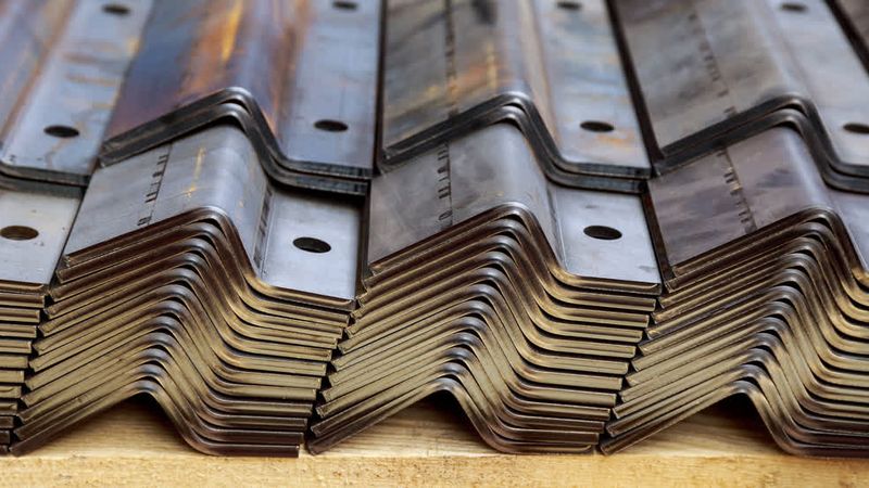
Types of Sheet Metal Fabrication Process
Sheet metal fabrication encompasses a variety of processes used to transform flat metal sheets into complex shapes and structures. It typically begins with the cutting of metal sheets to the required size. Then, techniques such as stamping, bending, and stretching are used to shape the metal into desired forms. Additional processes like welding, riveting, and fastening might be employed to assemble components. The final product may undergo finishing treatments, such as painting or coating, to enhance appearance and durability. Understanding the different fabrication techniques allows for the creation of everything from simple components to intricate assemblies, suitable for diverse industrial and commercial applications.
Sheet Metal Cutting Techniques
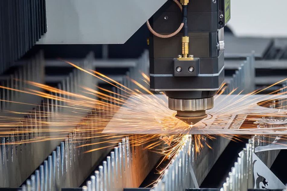
Laser Cutting Process
Laser cutting has revolutionized sheet metal manufacturing, offering unparalleled precision and efficiency. This advanced technique harnesses the power of focused light to melt, vaporize, or burn away material with remarkable accuracy. At its core, laser cutting employs a high-powered laser beam directed through optics to concentrate an immense amount of energy onto a small area of the metal sheet.
The process begins with a CAD file that guides the laser's path. As the beam moves across the sheet metal, it creates a narrow kerf, or cut width, resulting in clean, sharp edges. The intense heat generated by the laser beam instantly melts or vaporizes the metal, while a coaxial gas jet blows away the molten material, preventing it from re-solidifying in the cut zone.
The primary types of laser used in sheet metal manufacturing are:
Feature | CO2 Lasers | Fiber Lasers |
Material Composition | Gas mixture (CO2, nitrogen, helium) | Rare-earth elements (typically ytterbium) in a glass fiber |
Wavelength | 10.6 micrometers | 1.064 micrometers |
Ideal Applications | Cutting non-metal and organic materials | Cutting reflective metals like aluminum and copper |
Cutting Capabilities | Can cut thicker materials (up to 25mm steel) | Faster cutting speeds for thin to medium-thickness materials |
Efficiency & Operating Costs | Lower efficiency, higher operating costs | Higher efficiency, lower operating |
Advantages of Laser cutting Technique:
- Precision: It achieves tolerances as tight as ±0.1mm, ensuring high accuracy for components and parts, which is essential for applications with stringent dimensional requirements.
- Versatility: Complex shapes and intricate patterns can be easily achieved with laser cutting technology.
- Speed: Laser cutting processes materials quickly, particularly thin sheets, which enhances overall production efficiency and reduces lead times for manufacturing.
- Non-contact process: By using a focused beam of light, laser cutting avoids physical contact with the material, reducing the risk of mechanical stress, warping, or deformation.
- Automation potential: The technology integrates well with CNC systems, enabling precise, automated cutting and improving consistency and productivity in both high-volume and custom production runs.
- Edge Quality: Produces clean, smooth edges with minimal need for secondary finishing, reducing post-processing work and improving the overall quality of the final product.
- Minimal Waste: The precision of laser cutting allows for efficient material use and reduced scrap, contributing to cost savings and environmentally friendly manufacturing practices.
Laser cutting excels in industries requiring high precision and complex geometries. In aerospace, it's used to create intricate components for aircraft and satellites. The automotive sector leverages laser cutting for body panels and structural elements. Electronics manufacturers rely on laser precision for cutting circuit boards and smartphone chassis. Medical device production benefits from the sterile, burr-free cuts laser technology provides. The art world has embraced laser cutting for creating detailed sculptures and installations.
As laser technology continues to advance, with developments like ultra-short pulse lasers and green wavelength lasers, the capabilities and applications of laser cutting in sheet metal manufacturing are set to expand even further, pushing the boundaries of what's possible in metal fabrication.
Recommended reading: What Is CNC Laser Cutting
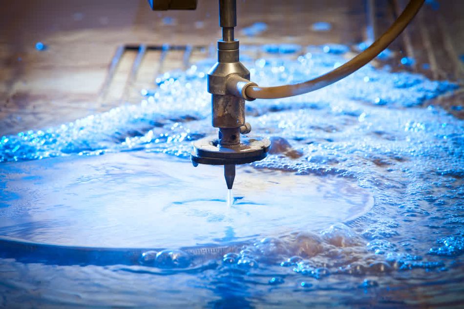
Waterjet Cutting Technique
Waterjet cutting is a versatile and powerful method in sheet metal manufacturing that utilizes a high-pressure stream of water to slice through materials with remarkable precision. This process harnesses the erosive power of water, accelerated to supersonic speeds, to cut through metal without introducing heat-affected zones or thermal distortion.
The core of waterjet cutting is a high-pressure pump that forces water through a tiny orifice in the cutting head, typically 0.1 to 0.4 mm in diameter. This creates a jet of water traveling at speeds up to 900 m/s, generating pressures between 30,000 and 90,000 PSI. The intense kinetic energy of this water stream erodes the material, creating a clean, precise cut.
Waterjet cutting is suitable for a wide range of materials and thicknesses. For metals, it can cut aluminum up to 200 mm thick, stainless steel up to 150 mm, and titanium up to 100 mm. In composites, it handles carbon fiber-reinforced plastics up to 100 mm thick. It is also effective on stone, cutting granite and marble up to 150 mm. Additionally, waterjet cutting can process glass up to 100 mm thick
There are two main types of waterjet cutting: pure waterjet and abrasive waterjet. Pure waterjet cutting uses only water and is suitable for softer materials like rubber, foam, and thin plastics. Abrasive waterjet cutting introduces fine abrasive particles, typically garnet, into the water stream. This significantly enhances the cutting power, allowing it to slice through harder materials like metals, ceramics, and composites.
Advantages of Waterjet Cutting in Sheet Metal Manufacturing:
Cold-cutting process: No heat-affected zones, preventing material deformation
Versatility: Cuts a wide range of materials and thicknesses
Precision: Achieves tolerances as tight as ±0.025 mm
Minimal material waste: Narrow kerf width reduces material loss
Environmentally friendly: Uses water as the primary cutting medium
Applications of Waterjet Cutting:
- Aerospace: Waterjet cutting is used for precision parts such as aircraft panels, engine components, and structural elements.
- Automotive: In the automotive industry, waterjet cutting is employed to produce components like brake discs, trim pieces, and engine parts.
- Marine: Marine applications benefit from waterjet cutting for creating hulls, deck fittings, and propeller blades.
- Electronics: Waterjet cutting is used to manufacture electronic enclosures, circuit board housings, and cooling plates.
- Architecture: In architecture, waterjet cutting is applied to fabricate intricate facade panels, decorative screens, and custom metalwork.
- Mining: Waterjet cutting assists in producing mining equipment components such as drill bits, wear plates, and conveyor parts.
- Food Processing: The food processing industry utilizes waterjet cutting for components like stainless steel processing plates and machinery parts.
- Medical Device Manufacturing: Waterjet cutting is used to produce precise medical device components, including surgical instruments and implants.
- Artistic and Decorative Metalwork: Artists and craftsmen use waterjet cutting for custom sculptures, signage, and decorative panels.
- Defense and Military Equipment Production: Waterjet cutting is employed to manufacture parts for military vehicles, weapon components, and protective armor.
As the technology continues to evolve, with advancements in pump efficiency and abrasive recycling systems, waterjet cutting is poised to play an even more significant role in shaping the future of metal fabrication.
Plasma Cutting Technology
Plasma cutting technology harnesses the power of ionized gas to slice through conductive materials with remarkable speed and precision. At its core, plasma cutting relies on the creation of an electrical arc between an electrode and the workpiece, which ionizes a gas (typically compressed air, nitrogen, or oxygen) to form plasma. This superheated plasma, reaching temperatures up to 30,000°C, melts the metal and expels it from the cut zone with high-velocity gas flow.
The science behind plasma cutting involves the fourth state of matter - plasma. When gas is heated to extreme temperatures and subjected to an electrical field, electrons are stripped from the atoms, creating a mixture of positively charged ions and free electrons. This ionized gas becomes electrically conductive, allowing it to carry an electrical arc and concentrate immense heat on a small area of the workpiece.
Types of Plasma Cutting Systems:
- Conventional Plasma: Uses a single gas for both plasma generation and shielding. Suitable for cutting materials up to 30mm thick with moderate precision.
- High-Definition Plasma: Employs a secondary gas flow to constrict the plasma arc, resulting in a narrower kerf and improved cut quality. Ideal for materials up to 25mm thick with high precision requirements.
- Precision Plasma: Utilizes advanced torch designs and gas mixing technologies to achieve laser-like cut quality on thin materials (up to 12mm).
- Underwater Plasma: Cuts material submerged in water, reducing noise, fume emissions, and UV radiation. Particularly useful for thick plate cutting.
Advantages of plasma cutting technology:
- Plasma cutting technology offers high cutting speeds, particularly effective for materials up to 25 mm thick.
- Plasma can cut a diverse range of conductive materials, making it versatile for various applications.
- The process provides good cut quality with minimal dross and a narrow kerf width, ensuring precise and clean edges.
- Plasma cutting is capable of cutting through stacked materials, increasing efficiency in processing multiple layers at once.
- This technology has relatively low operating costs compared to laser cutting, making it a cost-effective choice for many fabrication tasks.
Limitations of Plasma Cutting Technology:
- The plasma cutting technology is limited to conductive materials, it cannot cut non-conductive materials like plastics or ceramics.
- Plasma is less precise than laser cutting for very thin materials, which can affect the accuracy of cuts.
- Plasma cutting creates a wider heat-affected zone compared to laser cutting, which can impact the material's properties and finish.
- Difficulty in cutting very thick materials (greater than 50 mm) efficiently, often requiring additional processing or multiple passes.
Applications of Plasma Cutting Technology:
- Structural steel fabrication for construction
- Automotive body panel production
- HVAC ductwork manufacturing
- Shipbuilding and repair
- Heavy equipment manufacturing
- Scrap metal recycling
- Artistic metal sculpture creation
The versatility, speed, and cost-effectiveness of plasma cutting make it an indispensable technology in modern sheet metal fabrication.
Cutting Method | Precision | Speed | Material Range | Edge Quality | Operating Cost |
Laser Cutting | High | Fast | Wide | Excellent | Moderate |
Plasma Cutting | Moderate | Fast | Conductive only | Good | Low |
Waterjet | High | Slow | Very wide | Excellent | High |
Mechanical | Moderate | Varies | Limited | Fair | Low |
Recommended reading: What Is CNC Plasma Cutting
Advanced Forming Processes
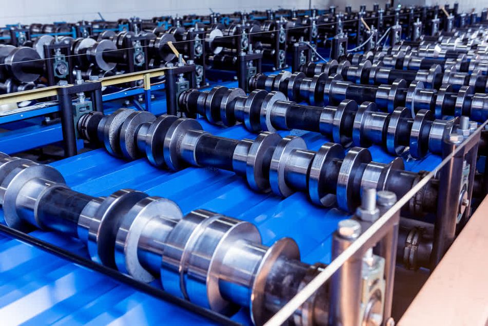
Roll Forming Process
Roll forming is a highly efficient, continuous metal forming process that transforms flat sheet metal into complex, long profiles with consistent cross-sections. This method excels in high-volume production scenarios, offering unparalleled speed and consistency for manufacturing long, linear components. In roll forming, a strip of metal is progressively bent as it passes through a series of precisely designed roller stations, each incrementally shaping the material until the final profile is achieved.
Advantages of Roll Forming:
- High production speeds, often exceeding 100 feet per minute
- Consistent quality across long production runs
- Ability to form complex profiles that would be challenging or impossible with other methods
- Minimal material waste compared to stamping or punching processes
- Capability to integrate in-line operations such as punching, notching, and embossing
- Suitability for a wide range of materials and thicknesses
Technical aspects of the roll forming:
The technical aspects of roll design and setup are important to the success of the roll forming process. Each set of rolls is custom-designed for a specific profile, requiring careful consideration of material properties, desired shape, and production requirements. The roll design process typically involves:
- Profile Analysis: Engineers analyze the desired cross-section to determine the number of forming stages required.
- Flower Pattern Design: A "flower pattern" is developed, showing the progressive bending of the metal at each stage.
- Roll Design: Individual rolls are designed using specialized software, considering factors such as material springback and minimum bend radii.
- Tooling Material Selection: Roll materials are chosen based on the workpiece material and production volume, with options ranging from mild steel to carbide-coated tools.
- Setup and Alignment: Precise setup and alignment of the roll stations are critical for achieving the desired profile and maintaining tight tolerances.
Applications of Roll Forming:
- Construction: Roll forming is used to produce roof and wall panels, structural framing members, gutters, and downspouts, offering durability and ease of installation.
- Automotive: In the automotive industry, roll forming creates door frames, window channels, bumper reinforcements, and body side moldings with consistent quality and precision.
- Aerospace: Roll forming is employed for manufacturing aircraft fuselage stringers and floor supports, which require high strength and lightweight properties.
- Appliances: The appliance industry utilizes roll forming for refrigerator door frames, oven liners, and washing machine drums, ensuring consistent quality and performance.
- Furniture: Roll forming is used to produce office partitions, shelving units, and display racks, providing versatility and structural integrity.
- Solar Energy: The roll forming technology is essential for solar panel frames and mounting systems, supporting and securing solar panels efficiently.
- Transportation: In transportation, roll forming creates truck trailer sides, railcar components, and shipping container parts, delivering strength and durability.
Key Considerations for Roll Forming Operations:
Material Selection: Choose materials with appropriate formability and consistent properties to ensure smooth and accurate roll forming.
Strip Width Calculation: Accurately determine the initial strip width to achieve the desired final profile dimensions.
Lubrication: Implement proper lubrication to reduce friction and improve the surface finish of the formed parts.
Tool Maintenance: Regularly inspect and maintain roll tooling to ensure consistent quality and prevent defects.
Process Monitoring: Utilize in-line measurement systems to detect and correct deviations in real-time, maintaining product accuracy.
Material Handling: Design efficient entry and exit systems to manage long, continuous products throughout the roll forming process.
Post-Forming Operations: Consider secondary processes such as cutting, punching, or welding when designing the production line to ensure seamless integration.
Tooling Changeover: Develop quick-change systems for efficient transitions between different profiles, minimizing downtime.
Quality Control: Implement rigorous quality checks, including dimensional verification and material testing, to ensure the final product meets all specifications.
Press brake forming operation
A press brake is a crucial machine in metalworking used for bending and shaping sheet metal. This process relies on the principle of plastic deformation, where a metal workpiece is placed between a punch and die, and force is applied to achieve precise angles and curves. The accuracy of the bend angle depends on factors such as material properties, tooling geometry, and the applied force.
Tooling and die selection are critical aspects of press brake operation. Punches and dies come in various shapes and sizes to accommodate different bend angles and material thicknesses. V-dies are the most common, with the V-opening width typically 8 to 10 times the material thickness for optimal results. Specialized tooling, such as gooseneck punches or hemming dies, allows for complex bend profiles and special operations.
Types of Press Brake Operation:
- Hydraulic Press Brakes: These machines use hydraulic cylinders to generate bending force. They offer high tonnage capabilities and are well-suited for heavy-duty applications. Hydraulic systems provide smooth, controlled movement and can maintain pressure for extended periods, making them ideal for complex bending operations.
- Electric Press Brakes: Utilizing servo motors to drive the ram, electric press brakes offer precise control and energy efficiency. They excel in high-speed, low-tonnage applications and provide faster cycle times compared to hydraulic systems. Electric press brakes are known for their repeatability and reduced maintenance requirements.
- Mechanical Press Brakes: These traditional machines use a flywheel and clutch mechanism to generate bending force. While less common in modern facilities, they still find use in specialized applications due to their high-speed capabilities and simplicity.
Feature | Hydraulic Press Brake | Electric Press Brake | Mechanical Press Brake |
Force Generation | Hydraulic cylinders | Servo motors | Flywheel and clutch |
Tonnage Range | High (up to 3000 tons) | Low to Medium (up to 300 tons) | Medium to High (up to 1000 tons) |
Speed | Moderate | High | Very High |
Energy Efficiency | Moderate | High | Low |
Precision | Good | Excellent | Moderate |
Maintenance | Regular | Minimal | Regular |
Noise Level | Low | Very Low | High |
Initial Cost | Moderate | High | Low |
Advanced Features of Press Brake Operation:
- CNC Control Systems: Modern press brakes incorporate sophisticated CNC units that allow for complex, multi-axis bending sequences. These systems can store numerous part programs, automatically adjust backgauges, and even simulate bending operations to detect potential collisions or errors before production begins.
- Angle Measurement Systems: Real-time angle measurement technologies, such as laser-based systems or contact sensors, provide instant feedback during the bending process. This allows for automatic angle corrections, ensuring consistent bend angles even with material variations.
- Crowning Systems: Adaptive crowning mechanisms compensate for machine deflection under load, ensuring uniform bend angles across long workpieces.
- Multi-axis Backgauges: Advanced backgauge systems with multiple axes of movement enable precise positioning of complex parts, facilitating the production of intricate geometries.
- Robotic Integration: Some press brakes can be integrated with robotic systems for automated part handling and bending, significantly increasing productivity in high-volume operations.
- Offline Programming Software: Sophisticated software packages allow operators to program complex bending sequences offline, optimizing machine utilization and reducing setup times.
These advanced features, combined with the fundamental principles of press brake bending, have transformed sheet metal forming into a highly precise and efficient process.
Stamping Process
Stamping is a fundamental sheet metal manufacturing process that transforms flat metal sheets into complex, three-dimensional parts through the application of force. This high-speed forming method utilizes specialized tools called dies to shape the metal, making it ideal for mass production of intricate components. The principle behind stamping involves placing a metal sheet (blank) between two halves of a die and applying pressure to deform the metal into the desired shape.
The stamping process can be broken down into several stages:
Blanking: The stamping process begins with blanking, where the initial shape is cut from the sheet metal.
Drawing: In the drawing stage, the blank is formed into a basic three-dimensional shape through applied force in a die.
Trimming: The trimming stage removes excess material to achieve precise dimensions and contours.
Piercing: During the piercing stage, holes or cutouts are created according to the design requirements.
Coining or Embossing: The coining or embossing stage adds fine details or textures to the surface, such as logos or functional patterns.
Quality Control and Inspection: Finally, a quality control and inspection phase ensures that the stamped parts meet all specified tolerances and performance requirements.
Different Types of Stamping Processes:
- Progressive Stamping: Utilizes a series of stations in a single die set, with each station performing a specific operation as the metal strip moves through the press. This method is highly efficient for high-volume production of small to medium-sized parts.
- Transfer Stamping: Employs multiple dies in sequence, with parts transferred between stations by an automated system. This process is suitable for larger, more complex parts that require multiple operations.
- Deep Draw Stamping: Specializes in forming deep, cup-shaped parts by drawing the metal into a cavity. This technique is commonly used for producing items like beverage cans and automotive body panels.
- Fine Blanking: A precision stamping process that produces parts with clean-cut edges, eliminating the need for secondary operations. It's ideal for components requiring high accuracy and smooth edges.
Critical Aspects for Die Design and Material Selection:
Determining the number of stages required to form the part
Calculating the forces and stresses involved in each operation
Designing the die geometry to achieve the desired part shape
Incorporating features for material flow control and scrap removal
- Common die materials include tool steel, carbide, and in some cases, advanced ceramics for specialized applications.
Advanced Stamping Technologies:
Servo Presses: These presses use servo motors instead of traditional flywheels, offering precise control over the ram's motion. Benefits include programmable stroke and velocity profiles, improved energy efficiency, reduced die wear and increased tool life, and the capability for complex motion sequences.
In-Die Sensors: Integrated sensors within the die provide real-time feedback on various process parameters. These include force monitoring to detect part defects or tool wear, material flow sensors to optimize blank positioning, and temperature sensors to monitor and control thermal conditions.
Simulation and Modeling Software: Advanced computer-aided engineering tools allow for virtual die tryouts to reduce physical prototyping, optimization of material flow and stress distribution, and prediction and mitigation of potential defects such as wrinkling or tearing.
High-Speed Vision Systems: Cameras and image processing software enable in-line quality inspection at production speeds, real-time adjustments to maintain part quality, and automated sorting of defective parts.
Smart Stamping Systems: Integration of IoT (Internet of Things) technologies enables predictive maintenance based on tool wear patterns, real-time process optimization using machine learning algorithms, and remote monitoring and control of stamping operations.
These advanced technologies have pushed the boundaries of what's achievable in stamping, enabling the production of increasingly complex parts with tighter tolerances and higher quality standards.
Comparison of Stamping, Press brake forming, Roll forming, and Hydroforming
Feature | Stamping | Press Brake Forming | Roll Forming | |
Production Speed | Very High | Moderate | Very High | |
Part Complexity | High | Moderate | Limited to Linear Profiles | |
Tooling Cost | High | Low to Moderate | High | |
Material Utilization | Moderate to High | High | Very High | |
Suitable Batch Size | Large | Small to Medium | Large | |
Dimensional Accuracy | High | Moderate to High | High | |
Material Thickness Range | Wide | Wide | Limited |
Joining Methods in Sheet Metal Manufacturing
Welding Technology
Welding is a critical process in sheet metal manufacturing, allowing for the permanent joining of metal components through the application of heat and pressure. This versatile technique enables the creation of complex structures and assemblies that would be impossible to achieve through forming alone. In sheet metal fabrication, several welding methods are employed, each with its unique characteristics and applications.
Key Welding Techniques:
- Metal Inert Gas (MIG) Welding: Also known as Gas Metal Arc Welding (GMAW), this process uses a continuously fed wire electrode and shielding gas. MIG welding is popular for its speed, versatility, and ability to weld a wide range of metal thicknesses.
- Tungsten Inert Gas (TIG) Welding: Also called Gas Tungsten Arc Welding (GTAW), TIG welding uses a non-consumable tungsten electrode and separate filler material. It produces high-quality, precise welds and is ideal for thin sheet metal and non-ferrous materials.
- Resistance Spot Welding: This process uses the heat generated by electrical resistance to create localized fusion between overlapping sheets. It's widely used in automotive manufacturing for joining body panels.
- Seam Welding: A variation of resistance welding that produces continuous, linear welds. It's commonly used for creating leak-tight joints in tanks and containers.
- Plasma Arc Welding: This technique uses a constricted arc to generate high heat concentration, allowing for deep penetration and high welding speeds on thin materials.
Advantages of Welding Sheet Metal:
- Welding sheet metal produces strong, permanent joints, ensuring the structural integrity of the assembly, which is essential for long-lasting applications.
- It allows the creation of complex assemblies, enabling intricate designs and structures that might not be possible with other joining methods.
- Welding is versatile in joining different thicknesses and materials, offering flexibility in design and manufacturing, which is crucial when working with varying materials in a single project.
- The process can be automated and scaled for high-volume production, making it suitable for industrial applications where efficiency and consistency are critical.
Challenges in Welding Sheet Metal:
- Heat distortion and warping are common issues, especially when welding thin materials, as excessive heat can deform the metal.
- Burn-through is a risk when working with very thin sheets, requiring precise control of the welding process.
- Welding dissimilar metals presents difficulties, as different metals may have incompatible properties, leading to weak joints.
- Skilled operators are essential, particularly for manual welding processes, where expertise is required to ensure high-quality welds and avoid defects.
Welding Method | Speed | Weld Quality | Material Thickness Range | Automation Potential | Cost |
MIG (GMAW) | High | Good | 0.5 - 13 mm | High | Moderate |
TIG (GTAW) | Low | Excellent | 0.2 - 6 mm | Moderate | High |
Resistance Spot | Very High | Fair | 0.5 - 3 mm | Very High | Low |
Seam Welding | High | Good | 0.5 - 3 mm | High | Moderate |
Plasma Arc | Moderate | Very Good | 0.5 - 6 mm | High | High |
Recommended reading: Plasma Arc Welding (PAW) Explained
Advanced welding technologies:
1. Laser Welding:
Laser welding produces precise, high-quality welds with minimal heat input, reducing thermal distortion. It is highly effective for welding thin materials at high speeds and is versatile enough to handle complex geometries and dissimilar materials.
2. Friction Stir Welding:
Friction stir welding joins materials without melting the base metals, resulting in low distortion and residual stress. It creates strong, durable welds and is particularly effective for materials that are challenging to weld using conventional methods.
3. Hybrid Welding:
Hybrid welding combines processes like laser and MIG to increase welding speed, improve weld quality, and ensure better penetration. It is effective for welding sections with varying thicknesses, offering greater flexibility and efficiency in manufacturing.
4. Adaptive Welding Systems:
Adaptive welding systems monitor and adjust welding parameters in real-time, ensuring consistent weld quality despite variations in part fit-up or material properties. This enhances reliability and reduces the need for rework.
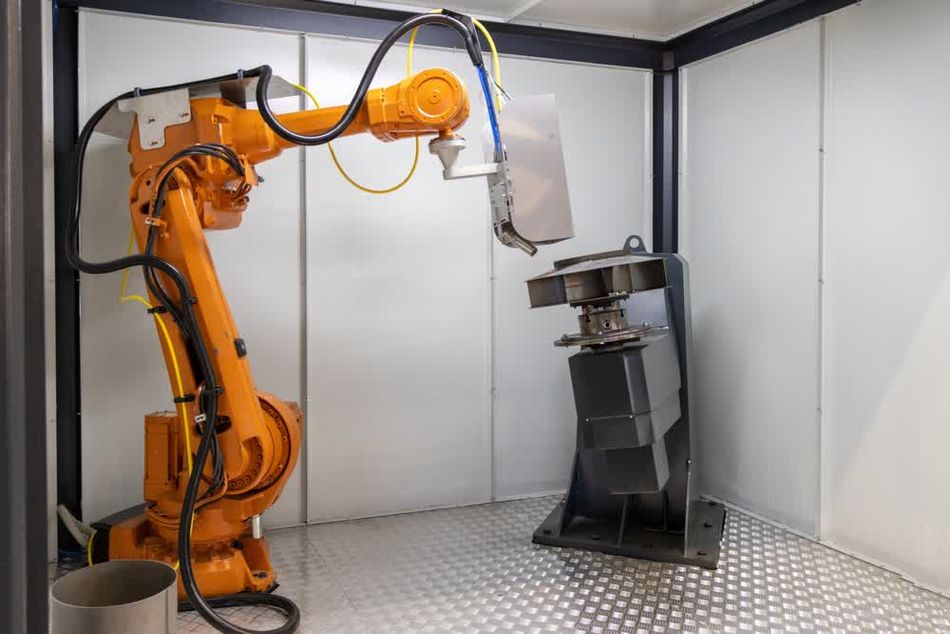
5. Robotic Welding with Advanced Sensors:
Robotic welding systems equipped with advanced sensors, such as vision and force sensors, offer precise seam tracking and adaptive path planning. These sensors enable the robotic arms to accurately follow complex weld paths, ensuring consistent weld quality across intricate assemblies. The integration of these advanced technologies increases productivity by allowing for higher levels of automation and repeatability, making robotic welding an essential component in modern manufacturing processes.
Recommended reading: Robotics and AI in sheet metal forming
Mechanical Fasteners
Mechanical fasteners play a crucial role in sheet metal assembly, offering versatile and reliable joining solutions across various industries. These components provide a means to securely connect metal parts without the need for welding or adhesive bonding, allowing for easier disassembly, maintenance, and part replacement when necessary.
Common types of Mechanical Fasteners:
- Screws: Thread-forming and thread-cutting screws are widely used for their ability to create their own mating threads in sheet metal. Self-drilling screws combine drilling and tapping operations, streamlining the assembly process.
- Bolts and Nuts: Ideal for applications requiring high strength and the ability to withstand dynamic loads. They offer excellent clamping force and are available in various grades and materials.
- Rivets: Solid and blind rivets provide permanent, high-strength joints. Blind rivets are particularly useful when access is limited to one side of the assembly.
- Push-in Fasteners: These include push nuts, spring clips, and retaining rings, offering quick installation and good retention in lightweight applications.
- Threaded Inserts: Used to create strong, wear-resistant threads in thin sheet metal, allowing for repeated assembly and disassembly.
Advantages of Mechanical Fastening:
Ease of Assembly and Disassembly: Facilitates maintenance, repair, and part replacement.
No Heat-Affected Zones: Unlike welding, mechanical fastening doesn't alter material properties.
Joining Dissimilar Materials: Allows for the connection of metals that are difficult or impossible to weld together.
Electrical Isolation: When using non-conductive fasteners, it's possible to join parts while maintaining electrical isolation.
Vibration Resistance: Certain fastener designs offer excellent resistance to loosening under vibration.
Critical Aspects for Fastener Selection and Installation:
- Material Compatibility: Choose fastener materials that are compatible with the sheet metal to prevent galvanic corrosion.
- Strength Requirements: Consider the load-bearing capacity needed for the application, including tensile, shear, and fatigue strength.
- Installation Method: Select fasteners based on the available installation tools and access to the joint.
- Hole Preparation: Proper hole sizing and preparation are essential for optimal fastener performance.
- Torque Control: For threaded fasteners, applying the correct torque is crucial to achieve the desired clamping force without damaging the components.
Factors to consider when choosing fasteners for sheet metal assembly:
- Material properties and sheet metal thickness
- Required joint strength and stiffness
- Environmental conditions (e.g., temperature, humidity, corrosive agents)
- Assembly and disassembly frequency
- Cost and availability of fasteners
- Aesthetic and design requirements
- Weight considerations
- Vibration and shock resistance
- Sealing requirements
- Regulatory compliance and industry standards
Advanced fastening technologies:
- Self-Piercing Rivets (SPR): This cold-forming process uses a semi-tubular rivet to join multiple layers of material without pre-drilled holes. SPR offers high-strength joints, is suitable for joining dissimilar materials, and causes minimal material distortion.
- Clinching: A method of joining sheet metal by local plastic deformation of the materials. It creates a mechanical interlock without additional fasteners or heat input. Clinching is fast, clean, and particularly useful for joining dissimilar materials.
- Flow Drill Screwing: Combines the processes of drilling and tapping into a single operation. The screw generates frictional heat as it penetrates the sheet metal, forming a cylindrical bush and creating its thread.
- Adhesive-Bonded Fasteners: Combine mechanical fastening with adhesive bonding, offering the benefits of both joining methods. This hybrid approach provides excellent strength, sealing properties, and vibration resistance.
- Smart Fasteners: Incorporate sensors or RFID tags to monitor joint integrity, preload, or environmental conditions. These advanced fasteners enable predictive maintenance and enhance safety in critical applications.
- Nano-coated Fasteners: Feature specialized coatings at the nanoscale to enhance corrosion resistance, reduce friction, or improve electrical conductivity.
These advanced fastening technologies continue to evolve, offering engineers new possibilities for creating stronger, lighter, and more efficient sheet metal assemblies across industries such as automotive, aerospace, and electronics manufacturing.
Adhesive Bonding Technique
Adhesive bonding offers unique advantages over traditional mechanical fastening and welding techniques. This process involves using specialized adhesives to create strong, durable bonds between metal surfaces, relying on chemical and physical interactions at the molecular level.
In sheet metal manufacturing, the principles of adhesive bonding are fundamental for creating strong and durable connections. The process begins with adhesion, which is the attraction between the adhesive and the substrate surfaces. This initial step is important, as it determines how well the adhesive will bond to the metal. Following adhesion, cohesion comes into play, representing the internal strength of the adhesive itself and its ability to maintain integrity under stress. Surface wetting is another important factor; it refers to the adhesive’s capability to spread over and make intimate contact with the substrate, ensuring a thorough and effective bond. Finally, curing is the process that transforms the adhesive from a liquid or paste into a solid state, which solidifies the bond and provides the required strength for the application.
Advantages of Adhesive joining:
- Uniform Stress Distribution: Adhesives distribute loads evenly across the entire bonded area, reducing stress concentrations.
- Joining Dissimilar Materials: Allows for the connection of metals with different thermal expansion coefficients or galvanic potentials.
- Lightweight Construction: Eliminates the need for heavy mechanical fasteners, contributing to weight reduction.
- Vibration Damping: Adhesives can absorb and dissipate vibrational energy, enhancing fatigue resistance.
- Sealing Properties: Many adhesives provide excellent sealing against moisture, gases, and contaminants.
- Design Flexibility: Enables joining of thin materials and complex geometries that may be challenging for traditional methods.
- Improved Aesthetics: Creates smooth, flush surfaces without visible fasteners or weld marks.
Factors for Adhesive Selection:
Consider factors such as substrate materials, operating environment, load requirements, and production constraints.
Common adhesive types for sheet metal include epoxies, acrylics, polyurethanes, and silicones, each with specific strengths and limitations.
Evaluate properties like strength, flexibility, temperature resistance, and cure time to match application needs.
Joining Method | Stress Distribution | Weight Impact | Joining Dissimilar Materials | Sealing Properties | Fatigue Resistance | Disassembly | Initial Equipment Cost |
Adhesive Bonding | Excellent | Low | Excellent | Excellent | Excellent | Difficult | Low to Moderate |
Welding | Poor to Fair | Low | Limited | Good | Fair | Impossible | High |
Mechanical Fasteners | Poor | Moderate | Good | Poor | Fair | Easy | Low |
Brazing/Soldering | Fair | Low | Good | Good | Good | Difficult | Moderate |
Advanced Adhesive Technologies:
- Structural Adhesives: High-performance adhesives designed to bear significant loads and replace or complement mechanical fasteners. They offer exceptional strength, durability, and resistance to environmental factors.
- Hybrid Joining: Combines adhesive bonding with mechanical fastening or welding, leveraging the strengths of multiple joining methods. This approach enhances overall joint performance, particularly in high-stress applications.
- UV-Curable Adhesives: Rapidly cure when exposed to ultraviolet light, allowing for fast production cycles and precise curing control.
- Thermally Conductive Adhesives: Incorporate fillers to enhance heat transfer, crucial for bonding heat sinks and electronic components in sheet metal assemblies.
- Nanoparticle-Enhanced Adhesives: Incorporate nanomaterials to improve strength, toughness, and electrical or thermal conductivity.
- Self-Healing Adhesives: Contain microcapsules or other mechanisms that release healing agents when cracks form, extending joint life and improving reliability.
- Smart Adhesives: Incorporate sensors or indicators to monitor bond integrity, cure status, or environmental conditions.
- Removable Structural Adhesives: Offer high strength during use but can be debonded on demand using specific triggers (e.g., heat, electrical current), facilitating repair and recycling.
These advanced adhesive technologies continue to expand the possibilities for sheet metal joining, enabling designers and engineers to create lighter, stronger, and more versatile assemblies across industries.
Advancements in Sheet Metal Manufacturing
Advancements in sheet metal manufacturing have increasingly involved the integration of cutting-edge technologies such as additive manufacturing, artificial intelligence (AI), and machine learning (ML). These technologies are not only revolutionizing traditional processes but also enabling new capabilities that were previously unattainable.
Additive Manufacturing Integration:
Additive manufacturing (AM), commonly known as 3D printing, is being integrated into sheet metal processes to complement and enhance traditional subtractive methods. This integration allows for the production of complex geometries and customized components that are difficult or impossible to achieve through conventional techniques. Notably, AM enables the production of topology-optimized parts, which can be integrated into sheet metal assemblies, potentially reducing weight and improving performance. This capability is especially advantageous in industries like aerospace and automotive, where weight reduction is critical for fuel efficiency and overall performance. Moreover, the combination of additive and subtractive manufacturing processes can lead to hybrid approaches, optimizing material usage and improving the overall efficiency of production.
Artificial Intelligence and Machine Learning:
AI and ML are increasingly being applied in sheet metal manufacturing to improve process optimization, quality control, and predictive maintenance. AI-driven algorithms can analyze vast amounts of data from production processes to identify patterns and anomalies, leading to more precise control over parameters such as temperature, pressure, and speed. This results in higher quality outputs and reduced waste. Machine learning models can also predict potential failures or defects in the manufacturing process, allowing for preventive actions to be taken before issues arise. This predictive capability not only enhances the reliability of production but also minimizes downtime, contributing to greater overall productivity.
The integration of these advanced technologies is setting new standards in sheet metal manufacturing, enabling more efficient, flexible, and intelligent production processes. As these technologies continue to evolve, they will likely lead to even more significant innovations in the field.
Recommended reading: How To Use AI ML To Optimise Manufacturing Costs
Quality Control Methods
In sheet metal manufacturing, dimensional accuracy is paramount to ensure the proper fit, function, and performance of the final product. Quality control processes employ a range of measurement and inspection techniques to verify that parts meet specified tolerances and maintain consistency across production runs.
Common Measurement and Inspection Techniques:
1. Manual Measurement Tools: These include calipers, micrometers, and dial indicators. Calipers are versatile tools used for measuring the internal, external, and depth dimensions of parts with moderate precision. Micrometers provide highly accurate measurements of small dimensions, typically used for thickness or diameter measurements. Dial indicators are used to measure deviations in surface flatness or alignment, making them useful for checking tolerances in machined parts.
2. Optical Comparators: These devices project magnified images of part profiles onto a screen, allowing operators to compare them against template overlays. This method helps in visually inspecting and measuring complex geometries and features, making it easier to identify deviations from design specifications.
3. Height Gauges: Used for precise vertical measurements, height gauges are essential for measuring stepped features or locating holes accurately. They work by sliding along a base surface while measuring the height of features with a fine scale or digital readout.
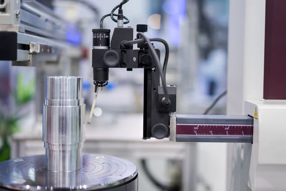
4. Coordinate Measuring Machines (CMMs): CMMs are automated systems that provide high-precision 3D measurements. They use a probe to touch various points on a part, gathering data that is then used to create a detailed 3D model. CMMs are particularly useful for inspecting complex parts with intricate geometries and tight tolerances. They provide highly accurate measurements (typically ±0.001 mm or better).
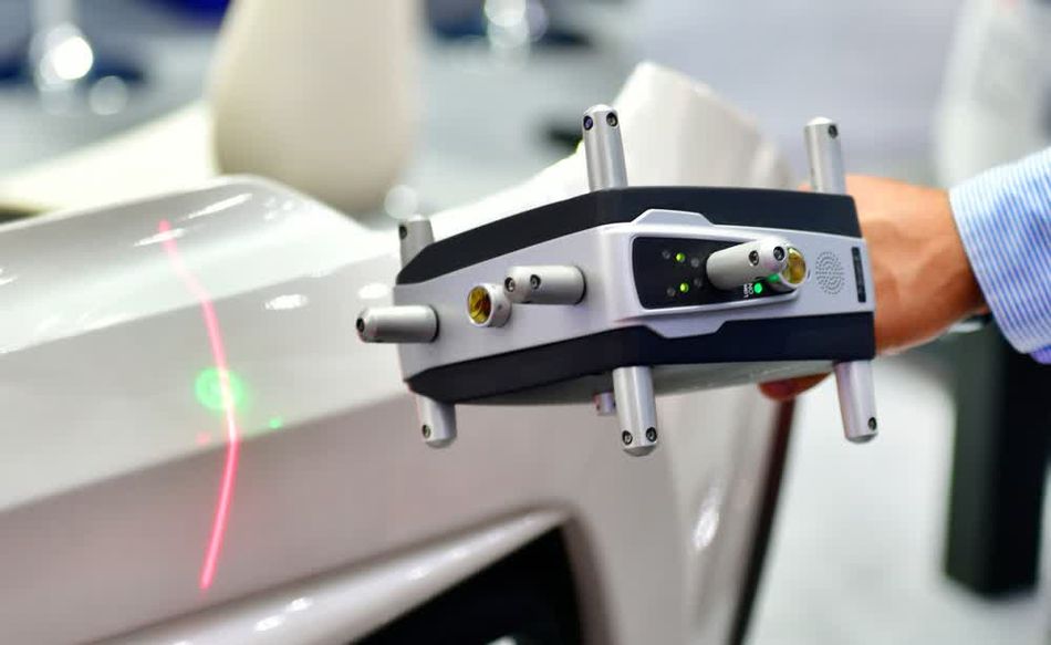
5. 3D Scanning: This non-contact measurement technique utilizes laser or structured light technology to capture detailed 3D shapes of objects. 3D scanning is ideal for capturing the full geometry of parts quickly and accurately, allowing for detailed analysis and comparison with CAD models.
6. Vision Systems: These systems use cameras to inspect parts for 2D measurements and surface defects. Vision systems can analyze images to detect irregularities such as scratches, dents, or other surface imperfections, and are often integrated with software for automated inspection and data analysis.
Each of these techniques plays a major role in maintaining the high standards required in sheet metal manufacturing, ensuring that parts meet exact specifications and function as intended in their final applications.
Recommended reading: How 3D Scanning And A CMM Can Perform Quick And Reliable Inspections
Advanced Measurement Technologies:
1. In-line Laser Inspection Systems have revolutionized real-time quality control by integrating directly into production lines. These systems employ multiple laser sensors to continuously measure critical dimensions of parts as they are produced. This real-time measurement capability allows for immediate feedback, enabling operators to make process adjustments on the fly. The continuous monitoring helps in the early detection of trends or deviations from specifications, which is crucial for maintaining high standards of production quality.
2. Structured Light 3D Scanners utilize advanced optical methods to capture detailed surface geometry. By projecting a pattern of light onto a part and using multiple cameras to analyze the distortion of this pattern, these scanners generate high-resolution 3D models almost instantly. This technology is particularly effective for the rapid inspection of complex geometries, providing a comprehensive view of the part’s surface and enabling quick identification of any discrepancies from the design.
3. Computed Tomography (CT) Scanning employs X-ray technology to create detailed cross-sectional images of parts. This method is invaluable for inspecting internal features and assemblies without disassembling them. CT scanning provides a detailed analysis of material density and can reveal internal defects, making it a critical tool for thorough quality control and ensuring the structural integrity of sheet metal components.
4. Non-Destructive Testing (NDT) is a critical aspect of quality control in sheet metal manufacturing, providing methods to evaluate the integrity of materials, components, and assemblies without causing any damage. NDT techniques are essential for detecting internal and surface defects, ensuring that components meet required specifications and perform reliably throughout their service life. These methods help manufacturers to verify weld quality, assess material properties, and prevent potential failures, ultimately contributing to safety and compliance with industry standards.
- Ultrasonic Testing (UT) is a widely used non-destructive testing method that employs high-frequency sound waves to inspect materials. In UT, a transducer generates sound waves that travel through the material. When these waves encounter interfaces or internal defects, they are reflected back to the transducer. By analyzing these reflections, technicians can determine the location, size, and nature of any flaws. UT is particularly effective for detecting internal defects such as cracks and voids, as well as measuring material thickness. It is valued for its ability to penetrate deep into materials and its sensitivity to small defects, making it crucial for applications like weld inspection and lamination detection in sheet metal.
- Radiographic Testing (RT) utilizes X-rays or gamma rays to create detailed images of internal structures within materials. In RT, radiation passes through the material and exposes a photographic film or digital detector on the other side. Variations in material density appear as contrast differences in the radiographic image, allowing for the detection of internal voids, inclusions, and other defects. This method provides a permanent record of the inspection, which is useful for documentation and quality assurance. RT is versatile and can be used on a range of materials, making it ideal for comprehensive inspection of welds and assemblies.
- Eddy Current Testing (ET) involves the use of electromagnetic induction to detect surface and near-surface defects in conductive materials. An alternating magnetic field is created by an induction coil, inducing eddy currents in the material. Disruptions in these currents, caused by defects or variations in material properties, affect the coil's impedance, which is then measured and analyzed. ET is known for its fast and sensitive detection capabilities, particularly for surface cracks and coating thickness measurement. It is effective for applications where rapid inspection and material sorting are required.
- Magnetic Particle Inspection (MPI) is a method used to identify surface and near-surface discontinuities in ferromagnetic materials. In MPI, the material is magnetized, and magnetic particles are applied to its surface. The particles are attracted to areas of flux leakage, such as cracks or other defects, making these imperfections visible. MPI is effective for detecting surface-breaking defects and is commonly used in weld inspection and quality control of ferromagnetic components. This method provides a straightforward and reliable means of ensuring material integrity.
- Liquid Penetrant Testing (PT) is used to reveal surface-breaking defects by applying a liquid dye to the material. The dye penetrates any surface cracks or voids due to capillary action. After a specified dwell time, excess dye is removed, and a developer is applied, which draws the trapped dye out of the defects and makes them visible against a contrasting background. PT is effective for detecting fine surface-breaking defects and is commonly used in conjunction with other NDT methods to ensure comprehensive inspection. This method is particularly useful for inspecting welds and other critical components where surface integrity is crucial.
- Phased Array Ultrasonic Testing (PAUT) utilizes multiple ultrasonic elements to electronically steer and focus the sound beam, significantly improving defect detection and characterization. This advanced technique allows for faster inspection of complex geometries and enhances imaging capabilities, making interpretation easier. PAUT reduces inspection time for large areas and is commonly used for weld inspection, corrosion mapping, and thickness profiling in sheet metal structures.
- Digital Radiography (DR) replaces traditional film with digital detectors, enabling faster image acquisition and processing. This technology supports real-time imaging and advanced image enhancement techniques, which streamline the inspection process and improve the clarity of results. DR offers quicker feedback and higher quality inspections, facilitating effective quality control.
- Guided Wave Testing employs low-frequency ultrasonic waves to inspect long distances, making it ideal for rapid screening of large areas such as piping or plate structures. This technique is effective for detecting corrosion and other defects over extensive surfaces without requiring disassembly, offering a broad-area inspection solution.
- Electromagnetic Acoustic Transducers (EMATs) generate ultrasonic waves directly in materials without contact, which is beneficial for high-temperature or rough surface inspections. This non-contact method is useful for inspecting challenging environments where traditional contact methods may not be feasible.
- Laser Shearography uses laser interferometry to detect surface deformations caused by internal defects. This technology is effective for identifying issues such as delaminations and disbonds in composite materials by detecting subsurface anomalies through surface-level inspections.
- Photogrammetry involves using high-resolution photographs to create three-dimensional models of large-scale parts or assemblies. This technique provides a portable solution for on-site measurements and is suitable for inspecting extensive components with precision.
- Robotic Inspection Systems integrate robotic arms with various sensors to enable flexible and automated inspection of complex parts. These systems can combine multiple inspection methods, including vision, touch probes, and laser scanning, for comprehensive and efficient analysis.
- Artificial Intelligence in quality control enhances defect detection and classification in visual inspection systems. By using adaptive algorithms and analyzing historical data, these technologies improve measurement accuracy and enable predictive quality control, pushing the boundaries of precision and efficiency in sheet metal manufacturing.
Conclusion
Sheet metal manufacturing plays a significant role in modern industrial production, utilizing innovative forming, cutting, and joining techniques. The versatility of sheet metal fabrication allows for the creation of complex, lightweight structures, which are essential in applications ranging from aerospace components to consumer electronics. The continuous evolution of technologies such as laser cutting, advanced forming processes, and precision measurement systems has expanded the possibilities for accuracy, efficiency, and design complexity.
The integration of automation, robotics, and artificial intelligence is revolutionizing sheet metal production, enhancing productivity and consistency while reducing waste and production costs. Emerging technologies like additive manufacturing and hybrid processes are blurring the lines between traditional sheet metal work and other manufacturing methods, opening up new possibilities for design and production.
The future of sheet metal manufacturing will be defined by the seamless integration of digital technologies, advanced materials science, and sustainable practices, driving innovation across industries and shaping the products of tomorrow.
Frequently Asked Questions
Q: What are the primary advantages of laser cutting over traditional cutting methods in sheet metal fabrication?
A: Laser cutting offers superior precision, faster cutting speeds for thin materials, and the ability to create complex geometries with minimal tooling changes. It also produces a narrow kerf width, reduces material waste, and minimizes heat-affected zones compared to plasma or flame cutting.
Q: How does the choice of material affect the sheet metal forming process?
A: Material properties such as yield strength, ductility, and strain hardening significantly influence formability. Softer materials like aluminum are generally easier to form but may require special handling to prevent surface damage. High-strength steels offer improved structural performance but may require higher forming forces and exhibit more spring back.
Q: How are emerging technologies like artificial intelligence and machine learning impacting sheet metal manufacturing?
A: AI and ML are enhancing various aspects of sheet metal production, including predictive maintenance of equipment, real-time quality control through computer vision systems, and optimization of process parameters. These technologies enable adaptive manufacturing processes that can automatically adjust to variations in material properties or environmental conditions.
Q: What are the key considerations when selecting a joining method for sheet metal assemblies?
A: Factors include material compatibility, joint strength requirements, production volume, accessibility, aesthetic considerations, and potential for disassembly. Engineers must also consider the impact on corrosion resistance, thermal expansion, and electrical conductivity. Advanced joining methods like structural adhesives or hybrid techniques may offer advantages in specific applications.
Q: How does additive manufacturing complement traditional sheet metal fabrication techniques?
A: Additive manufacturing, particularly metal 3D printing, can be used to create complex brackets, fittings, or custom tooling that interface with sheet metal components. It also enables the production of topology-optimized parts that can be integrated into sheet metal assemblies, potentially reducing weight and improving performance.
Q: How is automation integrated into modern sheet metal manufacturing processes?
A: Automation in sheet metal manufacturing is integrated through the use of advanced CNC machinery, robotic arms for material handling, and IoT-based monitoring systems that optimize workflow, reduce human error, and increase production efficiency.
Q: What future technological advancements are expected to drive innovations in sheet metal manufacturing?
A: Future advancements are expected in areas such as ultrafast laser technologies, AI-driven predictive maintenance, advanced material science for better formability, and the integration of additive manufacturing techniques with traditional sheet metal processes to expand design capabilities and reduce material waste.
Q: How do advanced quality control measures contribute to the reliability of sheet metal components?
A: Advanced quality control in sheet metal manufacturing includes the use of coordinate measuring machines (CMM), laser scanning, and in-process inspection systems to ensure components meet stringent dimensional tolerances and material specifications, reducing the risk of failures in critical applications.
References
[1] Altan T, Tekkaya AE. Sheet Metal Forming: Fundamentals. ASM International; 2012.
[2] Welo T, Chinesta F, Cueto E. Sheet Metal Forming. 2007. DOI: 10.1007/978-2-287-72143-4_10.
[3] Heidary M, Rübesam M, Rüter D, Himmel J, Kanoun O. Non-destructive testing for cracks in perforated sheet metal. 2011.
[4] Trzepieciński T. Recent developments and trends in sheet metal forming. Metals. 2020;10:779. DOI: 10.3390/met10060779.
[5] Rawat SS, Kumar Y, Dadge M. Detailed Study of Sheet Metal Forming Processes. Int J Adv Eng Manag. 2021;3(3):944-949. DOI: 10.35629/5252-0303944949.
[6] Trzepieciński T. Recent developments and trends in sheet metal forming. Metals. 2020;10(6):779. DOI: 10.3390/met10060779.
[7] Lim Y, Venugopal R, Ulsoy AG. Advances in the control of sheet metal forming. IFAC Proc Vol. 2008;41(2):1875-1883. DOI: 10.3182/20080706-5-KR-1001.00320.
Table of Contents
IntroductionTypes of Sheet Metal Fabrication ProcessSheet Metal Cutting TechniquesLaser Cutting ProcessWaterjet Cutting TechniquePlasma Cutting TechnologyAdvanced Forming ProcessesRoll Forming Process Press brake forming operationStamping ProcessJoining Methods in Sheet Metal Manufacturing Welding TechnologyMechanical FastenersAdhesive Bonding TechniqueAdvancements in Sheet Metal ManufacturingAdditive Manufacturing Integration:Artificial Intelligence and Machine Learning: Quality Control MethodsCommon Measurement and Inspection Techniques:ConclusionFrequently Asked QuestionsReferences