What is a CAN bus: The Backbone of Modern Vehicle Communication
Developed by Bosch in the 1980s, the CAN bus has become the nervous system of modern automobiles that facilitates seamless communication between the Electronic Control Units (ECUs). This article will decode CAN bus fundamentals, its functioning, variants, and advantages over other protocols.

16 Jul, 2024. 19 minutes read
Introduction
Controller Area Network (CAN) bus communication protocol has revolutionized vehicle electronics. From the engine control unit to the wiring harnesses of the airbag system, CAN bus standard interconnects many subsystems and coordinates to bring out a high performance. It has achieved this by significantly reducing wiring complexity, enhancing reliability, and facilitating efficient data exchange among vehicle components.
CAN bus's impact extends beyond automotive applications, finding widespread use in industrial automation, aerospace, and medical devices. It also provides a low-cost solution for the Internet of Things (IoT), thanks to companies like Intel which have integrated CAN bus into their microcontrollers. The protocol's ability to prioritize messages and handle error detection makes it indispensable in safety-critical systems. As vehicles become increasingly complex and connected, CAN bus continues to evolve, playing a crucial role in enabling Advanced Driver Assistance Systems (ADAS) and paving the way for autonomous driving technologies.
Decoding the CAN bus: Fundamentals and Architecture
What Makes CAN bus Tick: Core Components and Functionality
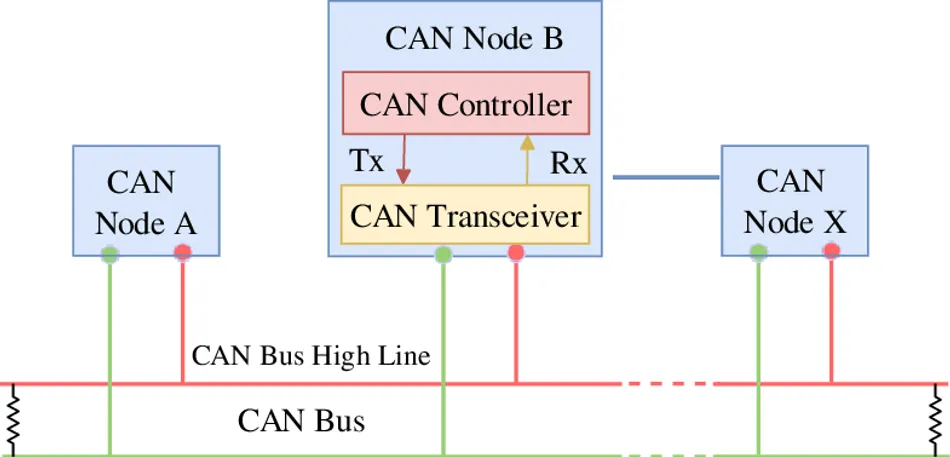
The Controller Area Network (CAN) bus is a vehicle bus standard that allows different car parts or industrial machinery to talk to each other efficiently. Released by Bosch in 1986 at the Society of Automotive Engineers (SAE), CAN bus has become the standard for in-vehicle networking because it’s reliable, flexible, and cost-effective. At its core, a CAN bus system consists of several key components:
- Nodes: These are the individual ECUs, sensors, or actuators connected to the network. Each node can send and receive messages independently.
- CAN Transceiver: These components interface between the CAN controller and the physical bus, converting digital signals to differential signals and vice versa. The connector used in a CAN bus system is crucial for its operation. It is responsible for facilitating the transmission of data between different nodes in the system.
- Terminators: 120-ohm resistors placed at each end of the bus to prevent signal reflections and ensure proper communication.
- CAN Bus Lines: Two wires, CANH and CANL, that carry the differential signals.
Data transmission in a CAN bus network occurs through a broadcast mechanism. When a node has to transmit data, it sends a message frame containing an identifier and the data payload. All nodes on the network receive this message, but only those programmed to recognize the specific identifier will process the data. This method allows for efficient, priority-based communication without the need for complex addressing schemes.
Key features of CAN bus include:
- Multi-master architecture: Any node can initiate communication when the bus is idle
- Broadcast communication: Messages are sent to all nodes simultaneously
- Message-based protocol: Data is transmitted in frames with unique identifiers
- Priority-based arbitration: Higher priority messages gain bus access during conflicts
- Error detection and handling: Built-in mechanisms for identifying and managing communication errors
- Fault tolerance: The system can continue operating even if one node fails
In the above diagram, multiple ECUs (nodes) are connected to the CAN bus lines (CANH and CANL). Each ECU contains a CAN controller and a transceiver, allowing it to communicate with other nodes on the network. The terminators at each end of the bus ensure signal integrity across the entire network.
Recommended Readings: Bus Topology: The Backbone of Simple Network Design
Recommended Readings: Types of Network Topology in Computer Networks
Under the Hood: CAN bus Layers and Protocols
The CAN bus works through two layers of the OSI (Open Systems Interconnection) model: the physical layer (described by ISO 11898-2) and the data link layer (described by ISO 11898-1). This architecture enables robust communication in noisy environments while maintaining simplicity and efficiency.
At the physical layer, CAN bus employs differential signaling over a twisted pair of wires. This configuration, consisting of CANH and CANL lines, provides excellent noise immunity and allows for reliable data transmission in electromagnetically noisy environments. The twisted pair wiring reduces electromagnetic interference (EMI) and crosstalk between adjacent wires. When idle, both lines maintain a voltage of about 2.5V. During signal transmission, CANH increases to about 3.5V while CANL decreases to about 1.5V, creating a 2V differential that represents a dominant bit (logical 0) [1].
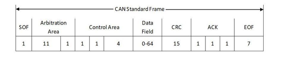
The data link layer of CAN bus is responsible for message framing, arbitration, and error detection. The data frame, the most common type, consists of several fields as will be discussed in the next section.
- Start of Frame (SOF): A single dominant bit indicating the start of transmission.
- Arbitration Field: Contains the message identifier and RTR (Remote Transmission Request) bit.
- Control Field: Specifies the number of data bytes and reserved bits.
- Data Field: Contains 0 to 8 bytes (CAN 2.0 or traditional CAN) or up to 64 bytes (CAN FD) of actual data.
- CRC Field: Cyclic Redundancy Check for error detection.
- ACK Field: Acknowledgment from receiving nodes.
- End of Frame (EOF): Seven recessive bits indicating the end of the frame.
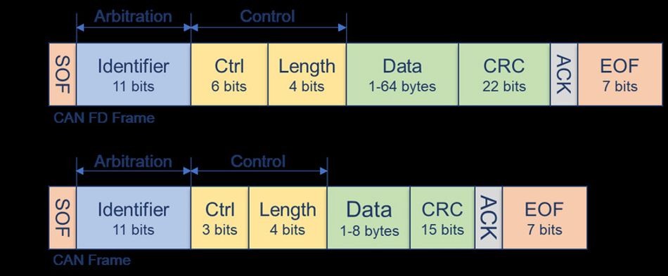
CAN protocol has 2 versions i.e. CAN 2.0 and CAN FD (Flexible Data-Rate). Here's a comparison between the two:
| Feature | CAN 2.0 | CAN FD |
| Max Data Field | 8 bytes | 64 bytes |
| Bit Rate (Arbitration) | Up to 1 Mbit/s | Up to 1 Mbit/s |
| Bit Rate (Data Phase) | Same as arbitration | Up to 8 Mbit/s |
| CRC Polynomial | 15-bit | 17 or 21-bit |
| Error States | Active, Passive, Bus-Off | Active, Passive, Bus-Off |
| Backward Compatibility | - | Partial (with CAN 2.0 controllers) |
Technical specifications for CAN bus include:
Data Rates:
- CAN 2.0: Up to 1 Mbit/s
- CAN FD: Up to 8 Mbit/s (data phase)
Maximum Bus Length:
- 40 meters at 1 Mbit/s
- 100 meters at 500 kbit/s
- 500 meters at 125 kbit/s
- 1000 meters at 50 kbit/s
These specifications allow for flexible implementation across various applications, balancing speed and distance requirements. The inverse relationship between data rate and bus length is due to signal propagation delays [2] and ensures reliable communication across different network configurations.
The Language of Machines: CAN bus Communication
Message Framing: CAN Bus Data Packaging
The Controller Area Network (CAN) protocol uses a sophisticated message framing structure to ensure reliable and efficient communication between nodes. The CAN message frame is the fundamental unit of data transmission in a CAN network, carefully designed to pack information into a compact and robust format.
A standard CAN message frame consists of the following components:
- Start of Frame (SOF): A single dominant bit (logical 0) that marks the beginning of the frame and synchronizes all nodes.
- Arbitration ID: An 11-bit (standard format) or 29-bit (extended format) identifier that determines the message priority and content.
- Remote Transmission Request (RTR): A single bit that distinguishes between data frames (dominant) and remote frames (recessive).
- Control Field: Includes the Identifier Extension (IDE) bit, reserved bit (r0), and Data Length Code (DLC) indicating the number of data bytes.
- Data Field: Contains 0 to 8 bytes of actual data to be transmitted.
- Cyclic Redundancy Check (CRC): A 15-bit error detection code followed by a delimiter bit.
- Acknowledgement (ACK) Field: Two bits where receiving nodes acknowledge successful reception.
- End of Frame (EOF): Seven recessive bits (logical 1) that mark the end of the frame.
Here's a visual representation of a standard CAN bus ata frame:
- Data Frame: The most common frame type, used to transmit data from a sender to receiver(s). Example: An engine control unit sending current engine temperature.
- Remote Frame: Used to request data from another node. It's similar to a data frame but with no data field and the RTR bit set to recessive. Example: A diagnostic tool requesting the current engine RPM.
- Error Frame: Transmitted when a node detects an error in communication. It consists of an error flag (6-12 consecutive dominant bits) followed by an error delimiter (8 recessive bits). Example: A node detecting a CRC mismatch and signaling an error.
- Overload Frame: Used to provide an extra delay between data or remote frames. It has a similar structure to the error frame but is transmitted under different conditions. Example: A node needing additional time to process received data before the next frame.
The CAN message frame structure enables efficient communication, built-in prioritization through arbitration IDs, and robust error detection mechanisms, making it suitable for real-time control systems in automotive and industrial applications.
Traffic Control: Arbitration and Collision Resolution
The Controller Area Network (CAN) bus employs a sophisticated arbitration process to manage simultaneous transmissions from multiple nodes. This process ensures efficient bus utilization, which is critical for real-time applications in automotive and industrial systems.
CAN bus arbitration is based on a non-destructive, bitwise arbitration method using message identifiers [3]. When multiple nodes attempt to transmit at the same time, the arbitration process determines which message gets priority without losing data or causing significant delays.
Message priorities are determined by the arbitration ID, which is part of the message frame. The arbitration ID consists of 11 bits in standard format or 29 bits in extended format. Importantly, a lower numerical value of the arbitration ID corresponds to a higher priority. This means that a message with an ID of 0x001 has a higher priority than a message with an ID of 0x100.
The non-destructive bitwise arbitration works as follows:
- When the bus is idle, any node can start transmitting.
- If multiple nodes start transmitting simultaneously, they begin by sending their arbitration IDs.
- Each transmitting node monitors the bus while sending its ID.
- If a node transmits a recessive bit (logical 1) but detects a dominant bit (logical 0) on the bus, it immediately stops transmitting and becomes a receiver.
- The node with the lowest arbitration ID (highest priority) continues transmitting without interruption.
To illustrate this process, consider the following example scenario:
- Node A: Arbitration ID 0x234 (binary: 001 0001 1100)
- Node B: Arbitration ID 0x352 (binary: 001 1010 1010)
Both nodes start transmitting simultaneously:
- Node A: 001 0001 1100
- Node B: 001 1010 1010
- Bus: 001 0001 1100
In this scenario, Node A wins the arbitration at the fourth bit position, where it transmits a '0' (dominant) while Node B transmits a '1' (recessive). Node B detects this conflict and immediately stops transmitting, allowing Node A to continue sending its message uninterrupted.
This arbitration method ensures efficient bus utilization and deterministic behavior in several ways:
- No time is lost in the arbitration process, as the highest priority message continues transmission without interruption.
- Lower priority messages automatically defer to higher priority messages, ensuring critical data is transmitted first.
- The process is deterministic, as the outcome of arbitration is always predictable based on the message IDs.
- Bus bandwidth is not wasted on collisions or retransmissions, as the arbitration process is non-destructive.
- The system naturally adapts to bus load, with higher priority messages always getting through even in high-traffic situations.
By using this arbitration method, CAN bus systems can guarantee that the most important messages are transmitted with minimal latency, even in complex networks with multiple nodes and varying message priorities. This makes CANs, defined by ISO 11898 and implemented by protocols like CANopen, particularly well-suited for real-time control systems where predictable, timely communication is essential. The connectors in the CAN bus system ensure the proper functioning and communication between various devices in the network.
Error Detection and Fault Tolerance
The Controller Area Network (CAN) bus, as outlined in the ISO 11898 standard, incorporates robust error detection mechanisms and fault tolerance features to ensure reliable communication in noisy environments. These capabilities are crucial for maintaining integrity in safety-critical applications such as automotive control systems.
CAN bus employs several error detection mechanisms [4]:
- Cyclic Redundancy Check (CRC): A 15-bit CRC field is included in each message frame. The transmitting node calculates the CRC based on the frame content, and receiving nodes verify it. An error is detected if the calculated CRC doesn't match the received CRC.
- Bit Stuffing: After five consecutive identical bits, a complementary bit is inserted. This ensures sufficient edges for synchronization and helps detect bit errors. Receivers check for proper bit stuffing and flag violations as errors.
- Acknowledgement (ACK): Receiving nodes acknowledge successful reception by overwriting the recessive ACK slot with a dominant bit. If the transmitter doesn't detect an acknowledgement, it assumes an error has occurred.
- Frame Check: The CAN controller checks for proper frame formatting, including the presence of required fields and correct bit values in specific positions.
CAN bus handles error confinement and fault tolerance through a sophisticated error management system. Each node maintains two error counters: Transmit Error Counter (TEC) and Receive Error Counter (REC). These counters are incremented when errors are detected and decremented after successful transmissions or receptions.
Different types of errors in CAN bus include:
- Bit Errors: When a transmitter detects a different bit value on the bus than what it transmitted
- Form Errors: Violations of the fixed frame format
- Stuff Errors: Violations of the bit stuffing rule
- CRC Errors: Mismatch between calculated and received CRC
- Acknowledgement Errors: Lack of acknowledgement from any receiving node
Based on the error counter values, a CAN node can be in one of three error states:
- Error-Active: The default state where a node can participate normally in bus communication. When an error is detected, the node transmits an active error flag (six dominant bits).
- Error-Passive: Entered when either error counter exceeds 127. In this state, the node can still transmit and receive messages but uses a passive error flag (six recessive bits) when reporting errors. It must also wait for additional bit times before transmitting.
- Bus-Off: Triggered when the TEC exceeds 255. In this state, the node cannot transmit messages or error frames. It can only recover after detecting 128 occurrences of 11 consecutive recessive bits, indicating an idle bus.
These error states and their implications ensure that faulty nodes are progressively isolated from the network, preventing them from disrupting communication. The error-active state allows for normal operation, the error-passive state reduces the impact of frequently erring nodes, and the bus-off state completely removes persistently faulty nodes from the network.
This multi-layered approach to error detection and fault tolerance makes CAN bus highly reliable, even in challenging environments with electromagnetic interference or potential hardware failures. It allows the network to continue functioning effectively, even when individual nodes experience issues, which is crucial for maintaining system integrity in critical applications.
CAN bus Variants: Evolving for Modern Demands
Standard CAN: The Original Workhorse
The Controller Area Network (CAN) protocol, originally developed by Bosch in the 1980s, has evolved to meet the increasing demands of modern automotive and industrial applications. Standard CAN, encompassing CAN 2.0A and CAN 2.0B specifications, forms the foundation of this widely adopted communication system. It utilizes a CANopen protocol that allows devices to communicate with each other using a high-speed can network.
CAN 2.0A, also known as Standard CAN or low-speed CAN, utilizes an 11-bit identifier in the arbitration field. This format allows for 2,048 unique message identifiers, although due to compatibility issues with certain old controllers, only identifiers 0 to 2,031 are typically used. CAN 2.0A is characterized by its simplicity and efficiency in systems with a limited number of nodes.
CAN 2.0B, or Extended CAN, or high-speed CAN, introduces a 29-bit identifier, significantly expanding the address space to over 536 million unique identifiers. This extended format consists of the original 11-bit base identifier followed by an 18-bit identifier extension. The increased identifier length in CAN 2.0B offers several advantages:
- Greater flexibility in complex systems with numerous nodes and data types
- Enhanced message prioritization capabilities due to the larger number of available identifier values
- Improved compatibility with future expansions and upgrades
The key difference between 11-bit and 29-bit identifiers lies in their impact on frame structure and system performance:
- Frame length: CAN 2.0B frames are longer due to the extended identifier, which can slightly reduce the maximum achievable data rate on the bus.
- Prioritization granularity: The 29-bit identifier allows for finer control over message priorities, beneficial in systems with diverse communication needs.
- Compatibility: While CAN 2.0B devices can generally communicate with CAN 2.0A devices, the reverse is not always true, as CAN 2.0A devices may encounter errors when handling the longer identifiers.
Standard CAN finds typical applications in:
- Automotive systems: Engine control units, transmission control, body electronics, and infotainment systems
- Industrial automation: Programmable logic controllers (PLCs), sensors, and actuators in manufacturing environments
- Medical equipment: Patient monitoring devices and diagnostic instruments
- Agricultural machinery: Tractor control systems and implement communication
Despite its widespread use, standard CAN has limitations:
- Data rate: Maximum bit rates typically range from 125 kbit/s to 1 Mbit/s, which may be insufficient for bandwidth-intensive applications.
- Payload size: The 8-byte maximum payload in standard CAN frames can be restrictive for larger data transfers.
- Network size: The number of nodes and bus length are limited due to signal propagation delays and electrical characteristics.
- Arbitration efficiency: In systems with heavy traffic, the arbitration process can lead to increased latency for lower-priority messages.
These limitations have driven the development of newer CAN variants, such as CAN FD and CAN XL, to address the evolving needs of modern systems while maintaining compatibility with the robust and reliable standard CAN protocol.
CAN FD: Faster Data for Complex Systems
CAN Flexible Data-Rate (CAN FD) represents a significant evolution of the classical CAN protocol, designed to meet the increasing demands of modern automotive and industrial networks. Developed by Bosch and released in 2012, CAN FD addresses the limitations of standard CAN while maintaining compatibility with existing CAN infrastructure.
CAN FD offers several key advantages over standard CAN:
Higher data rates: While standard CAN is limited to 1 Mbit/s, CAN FD supports data rates up to 8 Mbit/s during the data phase of transmission.
Increased payload size: CAN FD extends the maximum payload from 8 bytes in standard CAN to 64 bytes per frame.
Improved error detection: CAN FD incorporates enhanced cyclic redundancy check (CRC) mechanisms, reducing the risk of undetected errors.
Flexible bit rate switching: CAN FD allows for different bit rates during arbitration and data phases, optimizing bus utilization.
[The contrast between the data frames of CAN FD and standard CAN has already been illustrated earlier in this article]
CAN FD is particularly beneficial in scenarios that require high-bandwidth communication or the transmission of larger data packets. Some key applications include:
- ECU flashing and software updates: The increased payload and higher data rates of CAN FD significantly reduce the time required for in-vehicle firmware updates.
- Advanced Driver Assistance Systems (ADAS): CAN FD supports the high-speed, real-time data exchange necessary for complex ADAS functions.
- Infotainment systems: The higher bandwidth of CAN FD enables faster transmission of multimedia content and user interface data.
- Diagnostic data logging: CAN FD allows for more comprehensive and frequent data collection, improving vehicle diagnostics and predictive maintenance.
- Industrial automation: In non-automotive applications, CAN FD's higher data rates and larger payloads benefit robotics, manufacturing systems, and process control networks.
- Medical equipment: CAN FD's improved reliability and data capacity make it suitable for critical medical devices and imaging systems.
By offering increased bandwidth and larger payloads while maintaining the robustness and simplicity of the CAN protocol, CAN FD provides a cost-effective solution for modern communication needs in automotive and industrial applications. Its ability to coexist with standard CAN nodes also allows for gradual adoption, making it an attractive option for system upgrades and new designs alike.
Recommended Readings: CAN FD: Revolutionizing Automotive and Industrial Communications
Other CAN Variants: Specialized Solutions
As the demands on in-vehicle and industrial networks continue to evolve, specialized variants of the CAN protocol have emerged to address specific requirements. Two notable examples are Time-Triggered CAN (TTCAN) and CAN XL, each offering unique features to meet the needs of advanced applications.
Time-Triggered CAN (TTCAN)
Time-Triggered CAN (TTCAN) extends the classical CAN protocol designed to provide deterministic, time-triggered communication. TTCAN introduces a global time base and a predefined schedule for message transmission, making it particularly suitable for safety-critical and real-time applications.
Key characteristics of TTCAN include:
- Deterministic communication with guaranteed latency
- Cyclic and synchronized message transmission
- Support for both time-triggered and event-triggered messages
- Enhanced fault tolerance through temporal partitioning
- Compatibility with existing CAN hardware
TTCAN finds applications in:
- Automotive X-by-wire systems (e.g., steer-by-wire, brake-by-wire)
- Industrial control systems requiring precise timing
- Aerospace and aviation control systems
Extra Long CAN (CAN XL)
CAN XL (Extra Long) is the latest addition to the CAN protocol family, designed to meet the increasing bandwidth and payload requirements of modern automotive and industrial networks. CAN XL significantly expands the capabilities of CAN while maintaining backward compatibility with CAN and CAN FD.
Key features of CAN XL include:
- Increased payload size up to 2048 bytes per frame
- Data rates up to 10 Mbit/s
- Enhanced error detection with 32-bit CRC
- Support for switched networks and selective multicast
- Backward compatibility with CAN and CAN FD
CAN XL is particularly beneficial in:
- Advanced driver assistance systems (ADAS) and autonomous driving
- High-bandwidth sensor data transmission (e.g., cameras, lidars)
- In-vehicle infotainment and connectivity
- Industrial automation with large data set requirements
These specialized CAN variants demonstrate the protocol's adaptability to emerging technological challenges. By offering solutions for deterministic communication (TTCAN) and high-bandwidth data transfer (CAN XL), these variants extend the applicability of CAN technology to a broader range of advanced applications, ensuring its continued relevance in the evolving landscape of automotive and industrial communication systems.
Beyond CAN bus variants, there are non-can bus variants that are used in the automotive industry, the prominent ones being:
- LIN Bus: The LIN bus is often used to replace the CAN bus in scenarios where inexpensive implementation is a priority. It is particularly suitable for connecting components within a vehicle's network, especially for mechatronics nodes of automotive applications. The LIN bus is a single master and multi-slave bus, reducing the cost and complexity of implementation due to its single-wire interface
- FlexRay: FlexRay replaces the CAN bus in applications where high-speed, fault-tolerant, and deterministic communication is essential. It is commonly used in safety-critical and adaptive cruise control systems of luxury cars, meeting the high-speed requirements of various applications in an automobile.
- Automotive Ethernet: Automotive Ethernet is utilized to replace the CAN bus in situations where high bandwidth and fault tolerance are crucial. As the automotive industry embraces more advanced technologies, such as autonomous driving and connected infotainment systems, the need for higher data rates and bandwidth increases. Automotive Ethernet provides the necessary capabilities to support these demanding applications
Beyond Automobiles: CAN bus Applications Across Industries
Industrial Automation and Robotics
Beyond the automotive sector, CAN bus has found widespread adoption in industrial automation and robotics due to its robust communication capabilities and real-time performance. In manufacturing and process control environments, CAN bus offers several advantages:
- Noise Immunity: The differential signaling used in CAN bus provides excellent resistance to electromagnetic interference, crucial in noisy industrial settings.
- Real-time Capabilities: CAN's deterministic communication and priority-based arbitration ensure timely delivery of critical messages.
- Flexibility: Easy addition or removal of nodes allows for modular system design and scalability.
- Cost-effectiveness: Reduced wiring and standardized components lead to lower implementation and maintenance costs.
Common industrial applications of CAN bus include:
- Programmable Logic Controllers (PLCs): CAN bus enables efficient communication between PLCs and various field devices, facilitating distributed control systems.
- Sensor Networks: Multiple sensors can be connected to a single CAN bus, simplifying data collection in complex industrial processes.
- Motion Control Systems: CAN bus coordinates communication between motor drives, encoders, and controllers for precise motion control in robotics and automation.
- Industrial Robotics: Robot arms and end effectors utilize CAN bus for real-time coordination and control.
- Process Instrumentation: Flow meters, pressure sensors, and temperature controllers use CAN bus for reliable data transmission in process industries.
The CAN bus, a specialized digital system, has improved how industrial components work together, diagnose issues, and boost manufacturing efficiency. Its ability to reliably operate in tough environments and provide precise communication makes it ideal for many industrial uses [5].
Suggested Readings: What is a PLC (Programmable Logic Controllers): A Comprehensive Guide
Suggested Readings: Cobots vs Robots: Understanding the Key Differences and Applications
The CAN bus Advantage: Benefits and Limitations
Why Engineers Love CAN bus
The Controller Area Network (CAN) bus has become a favorite among engineers in automotive and industrial applications due to its numerous advantages. The key benefits of CAN bus include reliability, cost-effectiveness, and flexibility, which have contributed to its widespread adoption and longevity in the field.
Key advantages of CAN bus includes:
- Reliability
- Robust error detection and handling mechanisms
- High noise immunity due to differential signaling
- Deterministic communication with prioritized message arbitration
- Cost-effectiveness
- Reduced wiring complexity compared to point-to-point systems
- Standardized components leading to lower implementation costs
- Scalability allowing for easy system expansion
- Flexibility
- Multi-master architecture enabling distributed control
- Easy addition or removal of nodes without affecting the entire system
- Support for various data rates and bus lengths
These advantages translate to real-world improvements in several ways:
- Automotive safety systems: CAN bus's reliability ensures critical messages from systems like Anti-lock Braking Systems (ABS) and Electronic Stability Control (ESC) are transmitted with high priority and minimal latency.
- Industrial automation: The cost-effectiveness of CAN bus allows for the creation of complex control systems with numerous sensors and actuators without prohibitive wiring costs.
- Medical devices: The robust error handling of CAN bus ensures reliable communication in life-critical medical equipment, such as ventilators and patient monitoring systems.
Challenges and Limitations
Despite its many advantages, CAN bus does face certain limitations, particularly in the context of modern automotive and industrial applications with increasing data demands.
Key limitations of CAN bus:
- Bandwidth constraints: Standard CAN is limited to 1 Mbit/s, which can be insufficient for high-bandwidth applications like advanced driver assistance systems (ADAS) or infotainment.
- Security concerns: Traditional CAN bus lacks built-in security features, making it potentially vulnerable to cyber attacks in connected vehicle scenarios.
- Limited payload size: The 8-byte payload of standard CAN frames can be restrictive for certain applications requiring larger data transfers.
- Bus length limitations: The maximum bus length decreases as the data rate increases, potentially limiting the physical extent of the network in some applications.
These limitations are being addressed in newer variants of CAN and alternative technologies:
| Feature | CAN Bus | LIN Bus | FlexRay | Automotive Ethernet |
| Max Data Rate | 1 Mbit/s (CAN), 10 Mbit/s (CAN XL) | 20 Kbit/s | 10 Mbit/s | 100 Mbit/s - 10 Gbit/s |
| Cost | Low | Very Low | High | Medium |
| Complexity | Low | Low | High | Medium |
| Determinism | Yes | Yes | Yes | Partial (with TSN) |
| Payload Size | 8 bytes (CAN), 2048 bytes (CAN XL) | 8 bytes | 254 bytes | 1500 bytes (typical) |
| Security Features | Limited (improving) | Limited | Limited | Advanced |
| Adoption | Widespread | Widespread | Limited | Growing |
CAN FD (Flexible Data-rate) increases the maximum data rate to 8 Mbit/s and extends the payload size to 64 bytes.
CAN XL further increases payload size to 2048 bytes and supports data rates up to 10 Mbit/s.
Security enhancements like message authentication codes (MAC) and encryption are being implemented in some CAN implementations.
Comparison of CAN bus with other automotive networking technologies:
While CAN bus continues to evolve to meet modern demands, technologies like Automotive Ethernet are gaining traction for high-bandwidth applications. In some applications, standard CAN are often replaced by LIN bus protocol while CAN variants act as the best substitute. However, CAN bus remains a robust and cost-effective solution for many automotive and industrial applications, with its newer variants addressing many of its traditional limitations.
Conclusion
The Controller Area Network (CAN) bus has revolutionized communication in automotive and industrial systems since its introduction. Its robust design, featuring prioritized message arbitration, error detection, and fault tolerance, has made it a cornerstone of modern vehicle architecture and industrial automation. CAN bus's cost-effectiveness, reliability, and flexibility have contributed to its widespread adoption across various industries.
In contemporary engineering and vehicle design, CAN bus plays a crucial role in enabling advanced functionalities, from critical safety systems to complex powertrain management. Its ability to facilitate distributed control and real-time communication has been instrumental in the development of sophisticated automotive electronics and industrial control systems.
To meet the evolving demands of modern applications, CAN bus continues to evolve. Variants like CAN FD and CAN XL address limitations in data rate and payload size, while maintaining backward compatibility. These advancements ensure that CAN bus remains relevant in the face of increasing bandwidth requirements and complex system architectures.
As we move towards an era of connected and autonomous vehicles, CAN bus technology continues to adapt. While high-bandwidth applications may leverage complementary technologies like Automotive Ethernet, CAN bus's deterministic nature, robustness, and cost-effectiveness ensure its continued relevance in critical vehicle systems and industrial applications for the foreseeable future.
Frequently Asked Questions
What is the maximum data rate of CAN bus?
Standard CAN supports up to 1 Mbit/s, while CAN FD can reach 8 Mbit/s, and CAN XL up to 10 Mbit/s. The actual maximum rate depends on the bus length and implementation specifics.
How does CAN bus handle message collisions?
CAN bus uses a non-destructive bitwise arbitration process. When multiple nodes attempt to transmit simultaneously, the message with the highest priority (lowest identifier) wins access to the bus without data loss or significant delay.
Can CAN bus be used in applications outside of automotive industry?
Yes, CAN bus is widely used in industrial automation, medical equipment, aerospace, marine applications, and agricultural machinery due to its reliability and robustness in harsh environments.
How does CAN bus compare to Automotive Ethernet?
CAN bus offers deterministic communication and is cost-effective for control applications, while Automotive Ethernet provides higher bandwidth for data-intensive applications. CAN bus is simpler to implement but has lower data rates, whereas Automotive Ethernet offers higher speeds but with increased complexity.
What are the main security concerns with CAN bus?
Traditional CAN bus lacks built-in security features, making it potentially vulnerable to unauthorized access and message injection. However, newer implementations are addressing these concerns through message authentication, encryption, and intrusion detection systems.
References
[1] Huiwenedn. Physical Layers. Link.
[2] Dergipark. An in-depth analysis of CAN bit-timing and delay sources. Link
[3] EMS-wuensche. How the CAN network functions. Link.
[4] Csselectronics. CAN Bus Errors. Link
[5] Engineersgarage. CAN Bus Applications. Link
Table of Contents
IntroductionDecoding the CAN bus: Fundamentals and ArchitectureWhat Makes CAN bus Tick: Core Components and FunctionalityUnder the Hood: CAN bus Layers and ProtocolsThe Language of Machines: CAN bus CommunicationMessage Framing: CAN Bus Data PackagingTraffic Control: Arbitration and Collision ResolutionError Detection and Fault ToleranceCAN bus Variants: Evolving for Modern DemandsStandard CAN: The Original WorkhorseCAN FD: Faster Data for Complex SystemsOther CAN Variants: Specialized SolutionsTime-Triggered CAN (TTCAN) Extra Long CAN (CAN XL)Beyond Automobiles: CAN bus Applications Across IndustriesIndustrial Automation and RoboticsThe CAN bus Advantage: Benefits and LimitationsWhy Engineers Love CAN busChallenges and LimitationsConclusionFrequently Asked QuestionsReferences