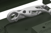
AR2 robotic arm
AR2 is an open source six-axis robotic arm actuated by motors and can be 3D printed.
Specifications
| Payload | 4.15 |
| 1.9 | |
| Reach | 24.75 |
| 69.2 | |
| Accuracy | 0.01 |
| Repeatability | 0.75 |
| Actuation | Method |
| Quantity | |
| Control | Arduino |
| Gripper | Type |
Overview
The AR2 is an open source project by Chris Annin which was uploaded to YouTube and GitHub. The AR2 is a multipurpose six-axis robotic gripper arm that can be programmed to perform various activities. The Robot is designed in such a way that it can be 3D printed and it can be manufactured in Aluminium.
Kinematics and CAD
Kinematics is the study of motion without considering the cause of the motion, such as forces and torques. Inverse kinematics is the use of kinematic equations to determine the motion of a robot to reach the desired position. For example, to perform automated bin picking, a robotic arm used in a manufacturing line needs precise motion from an initial position to the desired position between bins and manufacturing machines. The grasping end of a robot arm is designated as the end-effector. The robot configuration is a list of joint positions that are within the position limits of the robot model and do not violate any constraints the robot has.
 Conceptualization and CAD of the AR2
Once the robot’s joint angles are calculated using the inverse kinematics, a motion profile can be generated using the Jacobian matrix to move the end-effector from the initial to the target pose. The Jacobian matrix helps define a relationship between the robot’s joint parameters and the end-effector velocities.
Electrical and Electronics
The arm uses 6 Stepper motors and a separate motor for the track linear movement. The electronic control assembly is encased in an electrical enclosure box. The assembly consists of the channel relays, stepper motor drivers, one for each motor controlled by an Arduino Mega Micro-controller.
 Assembly of Stepper Motor Drivers.
A kill switch is installed on the top of the box to abort during an emergency or to kill power. Grippers can be either electric servo grippers or pneumatic grippers. If using a servo gripper, connect the servo to one of the Arduino analog pins 0 through 7 and then use the “Servo” position command button to control your gripper. If using a pneumatic gripper you would connect a 24 Volt DC solenoid valve to one of the relay outputs (Arduino outputs 38 through 45) and then use the “Set Output On” and “Set Output Off” commands to program relays to control your gripper.
Travel Track
The travel track is made out of aluminium and it is mounted on two linear motion guide rails. The track length in this project is 500 mm which can be increased as per user requirements. The material can be substituted using 3D printing considering the following precautions.
- 3D printed components require all threaded holes to be cleared with appropriate drill size.
- All printed components were printed at a minimum 50% solid at 2mm layer height and thick shells.
The linear motion of the track top is carried out by coupling stepper motor and a lead screw. The track is bolted to the lead nut and the guide rails provide constraint and structural support.
 Assembly of the Travel Track
References
Large collection of instruction videos regarding set up, software, and hardware.
Contains all the CAD and 3d files to replicate the arm. Describes how to start and calibrate the arm. Contains the bill of materials and instructions. Shows the Arduino sketch for stepper driver control and the software to program and operate the robot.
