Absolute Encoder: Precision Positioning in the Digital Age
Delve into the basics of absolute encoders, its applications, advancements in technologies, calibration techniques, and the advantages over encoder types.

21 Oct, 2024. 14 minutes read

Introduction
Absolute encoders are precision instruments that revolutionize position sensing in modern engineering. These sophisticated devices provide instant, accurate position information without the need for a reference point or movement. Unlike their incremental counterparts, absolute encoders maintain position data even when power is lost, offering unparalleled reliability in critical applications. Their ability to provide unique position values makes them indispensable in robotics, aerospace, and industrial automation, where precise motion control is paramount.
The robustness and accuracy of absolute encoders have led to widespread adoption in CNC machines, servo motors, and even renewable energy systems. As we delve deeper into the world of absolute encoders, we'll uncover the cutting-edge technologies that are pushing the boundaries of precision and redefining what's possible in position sensing.
Decoding the Basics: Absolute Encoder Fundamentals
The Anatomy of an Absolute Encoder
Absolute encoders are sophisticated position sensors that provide unique digital codes for each distinct position. The basic structure of an absolute encoder consists of a coded disc, a light source, and a series of photodetectors. The coded disc is the heart of the encoder, featuring a unique pattern of opaque and transparent segments arranged in concentric tracks.
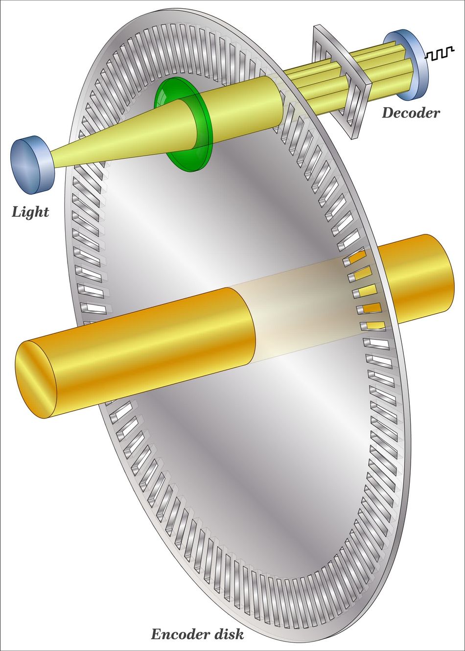
As the shaft rotates, the light passes through the coded disc's pattern, creating a unique combination of light and dark areas detected by the photodetectors. This combination is then translated into a digital code representing the absolute position of the shaft.
Absolute encoders come in three main types:
Optical Absolute Encoders - These use light transmission through a coded disc to determine position. They offer high precision and are widely used in industrial applications.
Magnetic Absolute Encoders -Utilizing a magnetized disc and Hall-effect sensors, these encoders are robust and resistant to contamination, making them suitable for harsh environments.
Capacitive Absolute Encoders - These use changes in capacitance to determine position. They are less common but offer advantages in certain applications due to their resistance to electromagnetic interference.
Each type has its strengths, and the choice depends on the application's specific requirements, such as precision, environmental conditions, and cost constraints.
To better understand the differences between absolute and incremental encoders, consider the following comparison:
Feature | Absolute Encoder | Incremental Encoder |
Position Information | Provides unique position value at all times | Provides relative position change |
Reference Point | No homing or reference point needed | Requires homing to establish reference |
Power Loss Handling | Retains position information | Loses position information |
Resolution | Fixed by disc design | Can be increased with interpolation |
Complexity | More complex, higher cost | Simpler design, lower cost |
Typical Applications | Critical positioning systems, robotics | General motion control, CNC machines |
This comparison shows the key advantages of absolute encoders in applications where immediate, accurate position information is crucial, especially in systems where power loss could be catastrophic.
Operating Principles: From Position to Digital Output
Absolute encoders employ a sophisticated mechanism to convert physical shaft position into precise digital signals. At the core of this process is a coded disc with multiple tracks, each representing a bit in the final digital output. As the shaft rotates, light passes through the disc's pattern and is detected by an array of photodetectors. The resulting combination of illuminated and dark sectors creates a unique binary code for each angular position.
The most common coding schemes used in absolute encoders are binary code and Gray code.
Binary code is straightforward, with each position represented by a unique binary number. However, it is prone to errors during transitions where multiple bits change simultaneously.
Gray code reduces the chances for errors by ensuring that only one-bit changes between adjacent positions, reducing the risk of misreadings during transitions.
Resolution and Accuracy
Resolution in absolute encoders is determined by the number of unique positions, graduations, or slots that can be encoded, typically expressed in bits. For instance, a 12-bit encoder can distinguish 4,096 (2^12) distinct positions within one revolution.
The accuracy of an absolute encoder, on the other hand, refers to how closely the reported position matches the actual physical position. It's influenced by factors such as disc manufacturing precision, alignment of optical components, and the quality of the signal-processing electronics.
How Absolute Position Measurement Helps
Key advantages of absolute position measurement include:
Immediate position information upon power-up without the need for homing or reference moves
Retention of position data even during power loss or system shutdown
Elimination of cumulative errors that can occur in incremental systems
Higher reliability in applications with frequent starts and stops or potential power interruptions
Suitability for safety-critical applications where precise position knowledge is essential at all times
The ability of absolute encoders to provide unambiguous position data makes them invaluable in applications ranging from industrial robotics to aerospace systems, where precise and reliable position feedback is crucial for operational safety and efficiency.
Recommended Reading: 7 Types of Industrial Robots: Advantages, Disadvantages, Applications, and More
Precision in Motion: Advanced Absolute Encoder Technologies
Multi-turn vs. Single-turn: Expanding the Range
Absolute encoders are categorized into two main types based on their range capabilities:
Single-turn Absolute Encoders - provide unique position information within one complete revolution of the shaft, typically offering resolution from 8 to 24 bits. These encoders are ideal for applications where the total range of motion is limited to one revolution or less.
Multi-turn Absolute Encoders - track multiple revolutions of the shaft, providing both the angular position within a single turn and the number of complete revolutions. This capability is crucial for applications involving multiple rotations, such as in robotics, wind turbines, or lift systems.
Multi-turn Encoders Applications
Multi-turn encoders are essential in various applications, including:
Industrial robotics: For precise arm positioning and movement tracking
Wind turbines: To monitor blade pitch and nacelle orientation
Packaging machinery: For accurate control of wrapping and sealing processes
Elevators and lifts: To track car position over multiple floors
CNC machines: For precise tool positioning in large work envelopes

The technology behind multi-turn functionality varies, with several innovative approaches:
Gear-based systems: These use a set of gears to track multiple revolutions, with each gear representing a different bit in the revolution count.
Battery-backed systems: These employ a small battery to power a counter that keeps track of revolutions, even when the main power is off.
Energy harvesting systems: These innovative designs use the motion of the shaft itself to generate power for the revolution counter, eliminating the need for batteries.
Magnetic systems: These use a combination of Hall-effect sensors and a magnetic element to detect and count revolutions without mechanical gears.
Suggested Reading: What is Magnetism? Examples of Magnetic Substances
The following table compares key specifications of single-turn and multi-turn absolute encoders:
Specification | Single-turn | Multi-turn |
Position range | 0 to 360 degrees | Multiple revolutions (e.g., 4096 revolutions) |
Typical resolution | 8 to 24 bits per turn | 12 to 24 bits per turn + 12 to 16 bits for turns |
Power-off behavior | Maintains position within one turn | Maintains position and revolution count |
Complexity | Lower | Higher |
Cost | Generally lower | Generally higher |
Size | Compact | Larger due to additional components |
Typical applications | Servo motors, short-stroke actuators | Robotics, long-range positioning systems |
Interface Innovations: Connecting Encoders to Control Systems
Modern absolute encoders employ a variety of sophisticated communication interfaces to transmit position data to control systems with high reliability and speed. The most prevalent digital interfaces include Synchronous Serial Interface (SSI), BiSS (Bidirectional Serial Synchronous), and EnDat (Encoder Data).
SSI is one of the earliest digital interfaces, which uses a simple clock and data line for unidirectional communication. It offers robust performance in noisy environments and is widely supported in industrial control systems.
BiSS is an open-source protocol, built upon SSI by adding bidirectional communication capabilities, allowing for encoder configuration and diagnostics.
EnDat was developed by Heidenhain, and provides high-speed, bidirectional communication with additional features like electronic datasheets and safety functions.
Digital interfaces offer several advantages over traditional analog outputs:
Improved noise immunity, allowing for longer cable runs without signal degradation
Higher resolution and accuracy, as digital signals can represent position data with more precision
Ability to transmit additional data such as temperature, diagnostics, and error flags
Reduced wiring complexity, often requiring only a single cable for power and data
Support for advanced features like electronic nameplates and on-the-fly configuration
A Technical Deep-dive into the BiSS Protocol
BiSS is an innovative approach to encoder communication. It operates in two modes:
BiSS-C (continuous) for cyclic data transfer
BiSS-A (acyclic) for parameter access -
BiSS achieves high data rates up to 10 MHz, allowing for rapid position updates crucial in high-performance motion control applications. Its open nature has led to widespread adoption and the development of BiSS Safety, which incorporates additional safety features for use in functional safety systems up to SIL 3 / PLe.
BiSS-C features a master (control system) initiates communication by sending a clock signal. The encoder (slave) responds by transmitting a start bit, followed by position data, error flags, and a cyclic redundancy check (CRC) for data integrity verification. The protocol supports daisy-chaining multiple encoders, reducing wiring complexity in multi-axis systems.
Data Transmission Process from Encoder to Control System
The following steps show the flow of data during a data transmission cycle.
The control system initiates communication by sending a request signal.
The encoder processes the request and prepares the position data.
The encoder transmits the data signal containing position information and potentially additional data like temperature or diagnostics.
The control system receives and decodes the data signal.
The decoded position information is used for motion control or other system functions.
The actual implementation of this process varies depending on the specific interface protocol used, with more advanced interfaces like BiSS or EnDat incorporating additional steps for error checking, bidirectional communication, and advanced features.
Pushing the Limits: High-Resolution and High-Speed Encoders
The demand for higher precision and faster response times in motion control systems has driven significant advancements in absolute encoder technology.
Advanced Optical Discs
One of the key technologies enabling higher resolution is the use of advanced optical discs with nanoscale patterns. These discs, manufactured using photolithography techniques borrowed from the semiconductor industry, can achieve pattern densities of up to 10,000 lines per inch. When combined with high-resolution image sensors and sophisticated signal processing algorithms, these encoders can provide position feedback with resolutions in the nanometer range.
Suggested Reading: Types of Sensors in Robotics
Capacitive Sensing
Another innovative approach is the use of capacitive sensing technology. By etching microscopic electrode patterns on a disc and measuring minute changes in capacitance as the disc rotates, these encoders can achieve extremely high resolution without the need for complex optics. This technology also offers advantages in terms of robustness and resistance to contamination.
Sub-Micron Precision
Achieving sub-micron precision presents several challenges, including thermal expansion, mechanical vibrations, and electromagnetic interference. Engineers address these issues through a combination of strategies:
Advanced error compensation algorithms that account for thermal effects and mechanical imperfections
Use of materials with low thermal expansion coefficients, such as Invar or ceramic
Implementation of active temperature control systems
Sophisticated mounting and isolation techniques to minimize the impact of vibrations
Electromagnetic shielding and differential signaling to reduce electrical noise
High-speed Data Transmission
High-speed data transmission is achieved through the use of advanced communication protocols and high-bandwidth interfaces. Some encoders now incorporate on-board processing capabilities, allowing for real-time error correction and data compression, which enables higher effective data rates without increasing raw bandwidth requirements.
Industries and applications requiring extreme precision or speed include:
Semiconductor manufacturing: Wafer positioning stages in photolithography equipment require nanometer-level precision and high-speed movement.
Suggested Reading: Wafer Backgrinding: An In-Depth Guide to Semiconductor Manufacturing
Aerospace: Satellite attitude control systems need highly accurate position feedback for precise pointing of communication antennas or scientific instruments.
Medical imaging: CT and MRI machines rely on high-resolution encoders for accurate patient positioning and image reconstruction.
Advanced robotics: High-precision robotic arms used in microsurgery or micro-assembly operations demand extremely accurate position feedback.
Particle accelerators: Beam steering and focusing systems require ultra-high resolution position control.

Overcoming Obstacles: Challenges in Absolute Encoder Implementation
Environmental Resilience: Conquering Harsh Conditions
Absolute encoders face significant challenges when deployed in extreme environments. These harsh conditions can include wide temperature fluctuations, intense vibrations, and exposure to contaminants such as dust, moisture, or corrosive chemicals. Temperature extremes can cause thermal expansion or contraction of encoder components, potentially leading to misalignment or changes in the gap between the sensor and the code disc.
Vibrations can induce mechanical stress, potentially causing fatigue failure or momentary misreadings.
Contamination can interfere with optical sensing systems or cause mechanical wear in moving parts.
To enhance encoder durability, manufacturers employ various technologies and design strategies:
Sealed Housings: Robust, hermetically sealed enclosures protect internal components from dust, moisture, and chemicals. Some designs achieve IP67 or even IP69K ratings for extreme washdown environments.
Temperature Compensation: Advanced algorithms and materials with low thermal expansion coefficients help maintain accuracy across wide temperature ranges.
Solid-State Designs: Encoders using capacitive or magnetic sensing technologies eliminate the need for optical components, reducing sensitivity to contamination.
Ruggedized Construction: Reinforced bearings, shock-absorbing mounts, and vibration-resistant circuit designs improve resilience to mechanical stress.
Specialized Coatings: Protective coatings on optical discs and electronic components enhance resistance to corrosion and wear.
The following table compares the environmental specifications of different absolute encoder models designed for harsh conditions:
Model | Temperature Range | Vibration Resistance | Ingress Protection | Special Features |
Heidenhain ROC 7000 | -40°C to +100°C | 300 m/s² | IP66 | Stainless steel housing |
BEI Sensors MHM5 | -40°C to +200°C | 250 g | IP68 | Pressure-resistant to 20,000 psi |
Leine & Linde 800 | -40°C to +85°C | 400 m/s² | IP67 | Heavy-duty bearings |
Renishaw RESOLUTE FS | -40°C to +80°C | 300 m/s² | IP64 | Non-contact optical reading |
Pepperl + Fuchs ENA58IL | -40°C to +85°C | 100 m/s² | IP69K | Washdown-resistant design |
This table illustrates the diverse range of environmental specifications available in modern absolute encoders, highlighting the industry's response to the demands of harsh operating conditions across various applications.
Calibration and Maintenance: Ensuring Long-term Accuracy
Proper calibration of absolute encoders is crucial for maintaining their high precision and reliability over time. Calibration ensures that the encoder's output accurately corresponds to the true position of the measured object, compensating for any mechanical or electrical deviations that may occur due to manufacturing tolerances, wear, or environmental factors.
Calibration procedures typically involve comparing the encoder's output to a known reference standard. This can be done using specialized calibration equipment such as precision rotary tables or linear stages with nanometer-level accuracy. For on-site calibration, portable laser interferometers or electronic levels may be used to verify encoder accuracy without removing the device from its installation.
Field calibration tools often include software interfaces that allow technicians to adjust offset and gain parameters, compensate for eccentricity, and fine-tune the encoder's output to match the reference standard. Some advanced absolute encoders incorporate self-calibration features, using built-in reference marks or multiple reading heads to continuously monitor and adjust their performance.
Preventive Maintenance
Preventive maintenance strategies play a vital role in extending the lifespan and maintaining the accuracy of absolute encoders. Regular inspections can identify potential issues before they lead to failures or inaccuracies. This may include checking for mechanical wear, ensuring proper alignment, and verifying signal quality. In harsh environments, particular attention should be paid to the integrity of seals and protective housings.
Best practices for maintaining absolute encoder accuracy include:
Establish a regular calibration schedule based on the encoder's specifications and the application's requirements.
Maintain detailed calibration records, including the date, the procedure used, and any adjustments made.
Use certified calibration equipment and follow manufacturer-recommended procedures.
Ensure proper environmental controls, such as temperature and humidity regulation, in the encoder's operating environment.
Regularly inspect mechanical couplings and mountings for signs of wear or misalignment.
Clean optical components using appropriate methods and materials to avoid damage.
Monitor encoder output signals for any signs of degradation or noise.
Implement condition monitoring systems to track encoder performance over time and predict maintenance needs.
Train maintenance personnel on proper handling and calibration techniques specific to absolute encoders.
Consider redundancy or backup systems for critical applications to minimize downtime during maintenance.
Conclusion
Absolute encoders provide instant, accurate position data without homing, revolutionizing motion control. Their high-resolution, versatile designs are used in various applications. Advanced features like multi-turn capability and communication protocols expand their applicability. As industries seek automation and precision, absolute encoders play a vital role. Future advancements in materials and AI will further enhance their capabilities, ensuring continued reliability and accuracy in position sensing.
Frequently Asked Questions
1. What is the difference between an absolute encoder and an incremental encoder?
Absolute encoders provide direct position readings without homing, making them ideal for applications requiring precise, immediate position information. Incremental encoders measure relative position and require homing. Absolute encoders are used in robotics, CNC machines, and factory automation, while incremental encoders are suitable for motor control and linear actuation.
2. How do absolute encoders maintain position information during power loss?
Absolute encoders maintain position information during power loss through various mechanisms:
Optical/Magnetic Discs: The physical position of the disc retains the last position.
Battery-backed systems: A small battery powers memory to store position data.
Energy harvesting technologies: Utilize motion to generate power for position retention.
Non-volatile memory: Some encoders use EEPROM or similar technology to store position.
Battery-backed systems provide reliable position retention but require periodic battery replacement. Energy harvesting solutions offer maintenance-free operation but may have limitations in static applications. Considerations for power-off scenarios include the duration of position retention and the potential need for brief movement upon power-up to confirm position in some designs.
3. What are the most common applications for absolute encoders?
Absolute encoders find widespread use across various industries:
Robotics: For precise arm positioning and joint angle measurement.
CNC Machines: Ensuring accurate tool positioning and workpiece location.
Aerospace: In-flight control systems and satellite positioning mechanisms.
Renewable Energy: For wind turbine pitch control and solar panel tracking.
Medical Equipment: In CT scanners and robotic surgical systems.
Automotive: In steering angle sensors and autonomous vehicle systems.
Material Handling: For crane positioning and conveyor systems.
4. How do you choose the right resolution for an absolute encoder?
Selecting the appropriate resolution for an absolute encoder involves several factors:
Application precision requirements
System mechanical characteristics
Control system capabilities
Environmental conditions
Guidelines for matching resolution to application needs:
Determine the smallest movement increment required for the application.
Consider the overall range of motion to ensure sufficient bits for full coverage.
Account for any gear ratios or mechanical linkages in the system.
5. Can absolute encoders be used in safety-critical systems?
Absolute encoders are indeed used in safety-critical systems, subject to stringent safety standards and certifications:
Safety standards: IEC 61508 (Functional Safety), ISO 13849 (Machine Safety)
Certifications: SIL (Safety Integrity Level), PL (Performance Level)
Examples of safety-critical systems using absolute encoders:
Elevator positioning systems
Industrial robot safety monitoring
Railway signaling and train control
Aircraft flight control surfaces
Special considerations for safety applications:
Redundancy: Use of dual encoders or internal redundant sensing elements.
Diagnostics: Continuous self-monitoring and error detection capabilities.
Fail-safe design: Ensuring predictable and safe behavior in case of failure.
References
Table of Contents
IntroductionDecoding the Basics: Absolute Encoder FundamentalsThe Anatomy of an Absolute EncoderOperating Principles: From Position to Digital OutputResolution and AccuracyHow Absolute Position Measurement HelpsPrecision in Motion: Advanced Absolute Encoder TechnologiesMulti-turn vs. Single-turn: Expanding the RangeMulti-turn Encoders ApplicationsInterface Innovations: Connecting Encoders to Control SystemsA Technical Deep-dive into the BiSS ProtocolData Transmission Process from Encoder to Control SystemPushing the Limits: High-Resolution and High-Speed EncodersAdvanced Optical DiscsCapacitive SensingSub-Micron PrecisionHigh-speed Data TransmissionOvercoming Obstacles: Challenges in Absolute Encoder ImplementationEnvironmental Resilience: Conquering Harsh ConditionsCalibration and Maintenance: Ensuring Long-term AccuracyPreventive MaintenanceConclusionFrequently Asked Questions1. What is the difference between an absolute encoder and an incremental encoder?2. How do absolute encoders maintain position information during power loss?3. What are the most common applications for absolute encoders?4. How do you choose the right resolution for an absolute encoder?5. Can absolute encoders be used in safety-critical systems?References