Building Power and Protection Circuits for Vehicle Asset-Tracking Devices
Article #6 of Power Management for Tomorrow’s Innovations Series: Power supplies for vehicle asset-tracking devices must be designed to operate at different voltage-current levels, be compact, and offer protection during transients and electrical faults.

Image credit: WikiMedia Commons
This is the sixth article in an 8-part series featuring articles on Power Management for Tomorrow’s Innovations. The series focuses on power management and optimization techniques for modern electronic systems. This series is sponsored by Mouser Electronics. Through the sponsorship, Mouser Electronics shares its passion for technologies that enable smarter and connected applications.
Vehicular asset tracking is an essential part of fleet management, providing a way to know the exact location of physical assets around the clock. The three main benefits of asset tracking are cost savings, theft protection, and preventative maintenance.
This article describes how to power asset-tracking devices with small, efficient power solutions and protect them from electrical stresses in a vehicular environment adequately.
Power Requirements for Vehicular Asset-Tracking Devices
Vehicular asset-tracking/fleet-management devices are powered by the vehicle battery, typically 12V in cars and 24V in many trucks. As an aftermarket add-on, they face a much harsher power management environment than a well-bounded OEM device.
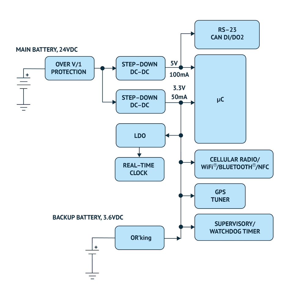
Most devices also have a rechargeable battery, typically 3.6V, intended to last two or three days when the main battery power is lost. The primary battery source protects the front-end electronics against transient and fault conditions. The protected voltage gets converted to usable, lower voltages (5V, 3.3V, 2.5V, or 1.2V) by step-down DC-DC converters and Low Dropout Regulators (LDOs) to power various digital logic and analog Integrated Circuits (ICs). Fig. 1 shows the architecture of a typical power system for asset-tracking/fleet-management devices.

Powering the Device with Modern DC-DC Regulators
Asset-tracking/fleet-management devices must be physically small to fit in small places. In such a small area, reducing heat dissipation in a device to keep its temperature within range is challenging. Fitting the power circuit into a small space requires highly efficient integration.
Modern DC-DC regulator power solutions that effectively integrate the power MOSFETs, compensation circuits, and other external components help reduce overall circuit size. Combining the small solution size with the efficient synchronous rectification technology helps reduce power dissipation.
One might consider employing LDOs here for small size since LDOs are generally low cost and very simple to use, but they have high power dissipation if used directly from the primary battery voltage, which is the main drawback. Dissipating this power in a small asset-tracking device may be impractical and may cause device overheating. Hence, a solution that meets both size and power dissipation requirements is preferred.
Protecting the Device from Faults
Electronic components can occasionally encounter faults. Short-circuit and overcurrent protection circuitry is essential for preventing fire hazards and isolating the power cable from a failed-short device.
When the ambient temperature becomes excessive or if there is an overcurrent or some other fault, the overtemperature protection prevents permanent damage by either scaling down the power or shutting down the device completely. Overtemperature protection prevents system overheating and fire hazards. It also ensures that the system operates within its defined temperature limits.
Reverse voltage faults occur when the battery gets connected in reverse or the power cable is installed backward. While unlikely to happen, reverse voltage faults usually cause extensive damage to the power cables and electronic devices connected to the cable without proper reverse voltage protection.
Electronic Solutions by Analog Devices for Powering and Protecting the Vehicular Asset-Tracking Devices
To increase integration and reduce the physical size of the power supply, Himalaya uSLIC™ power modules by Maxim Integrated (a part of Analog Devices) integrate the power inductor and other discrete components with the DC-DC regulator. These easy-to-use, easy-to-design, and quick-time-to-market power module solutions only require an input capacitor, an output capacitor, and an optional soft-start setting capacitor to complete the power solution.
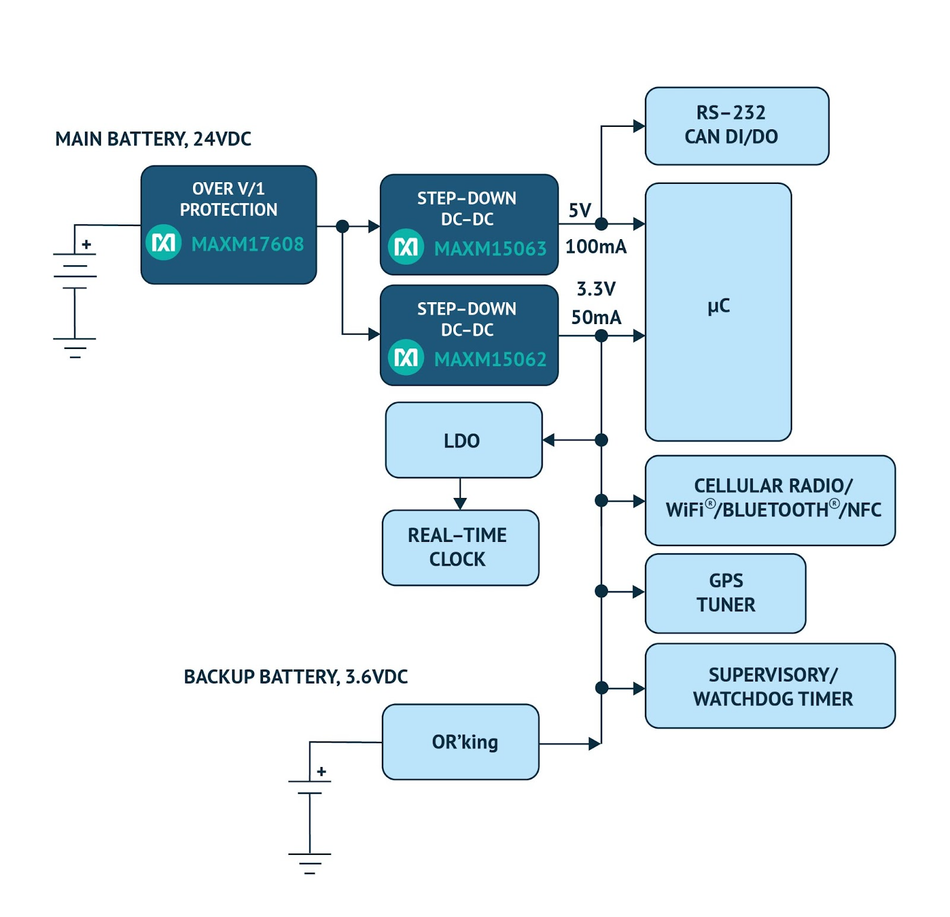
The micro-sized system-level Integrated Circuit (uSLIC™) family employs advanced packaging technology to minimize the module footprint. For example, the modules fit a 60V, 300mA power solution into a tiny, 2.6mm x 3mm x 1.5mm power module. This highly efficient synchronous DC-DC buck power module also minimizes heat dissipation in end equipment. The MAXM15062 has a fixed 3.3V output, while the MAXM15063 is similar but with a fixed 5V output. We employ these two modules to power our example asset-tracking/fleet-management device shown in Fig. 4.

The MAXM15062/MAXM1563 uSLIC™ power module fits the bill here. Total power dissipation employing the uSLIC™ power modules provides an 18x power dissipation reduction compared to the LDOs solution. Low power dissipation also means lower system operating temperature and higher long-term reliability.
For protecting the asset-tracking device, Analog Devices AX17608 60V/1A current limiter is a highly integrated IC that packs all necessary protections into a single, tiny 3mm x 3mm, 12-pin TDFN package.

Some features of the MAX17608 are:
High input voltage tolerance (+4.5V to +60V operating range)
Reverse voltage protection (tolerates -60V negative input voltage)
Reverse current protection
Short-circuit overcurrent protection
Adjustable OVLO, UVLO, startup current, and forward current limit
Overtemperature protection

Conclusion
Vehicular asset-tracking/fleet-management devices are designed to operate from the vehicle’s 12V/24V battery system and must fit in small places. They must be robust against transient conditions, including overvoltage, overcurrent, reverse voltage, reverse current, and overtemperature.
Highly integrated and efficient uSLIC power modules ensure fit, mitigate thermal dissipation challenges, and enhance the long-term reliability of the device. Highly integrated protection ICs, on the other hand, provide all the necessary protections mentioned above and simplify the design over discrete solutions.
This article is based on an e-book by Mouser and Maxim Integrated (a part of Analog Devices). It has been substantially edited by the Wevolver team and Electrical Engineer Ravi Y Rao. It's the sixth article from the Power Management for Tomorrow’s Innovations Series. Future articles will introduce readers to some more power management and optimization techniques for modern electronic systems.
The introductory article covered the fundamentals of power electronics, the technology behind highly-efficient power conversion in different electrical/electronic systems.
The first article shares some design techniques for efficient power management in EVs. It covers how manufacturers can build significantly better vehicular electric power systems with systematic planning and innovative power electronic solutions.
The second article introduced readers to silent switching and how it prevents EMI at the source, rather than adding shields and filters to the product later.
The third article describes current measurement techniques using LTC297x series components by Analog Devices. It presents some application circuits and compares different approaches for current sensing in power electronic converters.
The fourth article discussed the problems associated with phase noise and experimentally showcased how power supply designs can be optimized to deal with them.
The fifth article featured Single-Inductor Multiple-Output architecture that integrates different power supply functionalities to drastically reduce the overall size and costs for wearables.
The sixth article describes how vehicular asset-tracking devices are powered with small, efficient power solutions and protected from electrical stresses.
The seventh article explains how designers can implement and validate proven power supply circuits for enabling the reliable operation of healthcare devices.
The final article dealt with a specific IoT power management solution for small, and portable gadgets. It showcases a nano-Power boost converter that ‘operates on fumes’ to make the most out of all the available energy.
About the sponsor: Mouser Electronics
Mouser Electronics is a worldwide leading authorized distributor of semiconductors and electronic components for over 1,100 manufacturer brands. They specialize in the rapid introduction of new products and technologies for design engineers and buyers. Their extensive product offering includes semiconductors, interconnects, passives, and electromechanical components.
References
[1] Protect and Power Vehicular Asset-Tracking Devices - Application Notes, Maxim Integrated, [Online], Available from:

