Diode, Anode, Cathode: Unlocking the Power of Semiconductor Junctions
This article delves into the intricacies of diode, anode, cathode, and polarity, exploring the fundamental principles that drive countless electronic devices and systems, shaping the technological landscape we navigate daily.

19 Aug, 2024. 17 minutes read
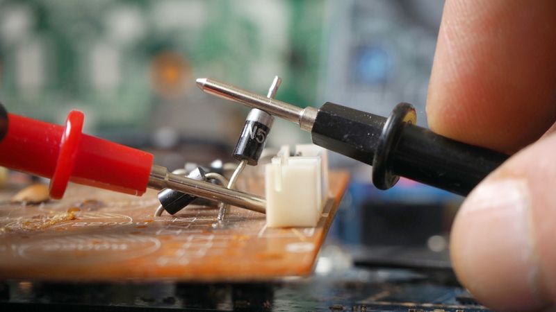
Technician Testing Diode on Printing Circuit Board
Introduction
The concepts of diode, anode, cathode, and polarity are foundational to electronics. Diode, a two-terminal electronic component, is constructed from a semiconductor material and exhibits a unique electrical characteristic: unidirectional current flow. This property is essential for a wide range of electronic applications, including rectification, voltage regulation, and signal processing.
The behavior of a diode is determined by the interplay between its two terminals: the anode and the cathode. The anode, typically represented by a positive voltage, allows current to pass through the diode. Cathode, on the other hand, is associated with a negative voltage and restricts current flow in the opposite direction. Understanding the intricate relationship between diode, anode, cathode, and polarity is vital for engineers working in fields ranging from power electronics to signal processing.
Still, curious about the complexities of diode, anode, cathode, and polarity? First, let’s get into the anatomy of a diode!
The Anatomy of a Diode: Anode and Cathode Unveiled
The Anode: Positive Powerhouse
The anode is a crucial component of a diode, serving as the positive terminal and the entry point for conventional current flow. In the context of semiconductor diodes, the anode is typically the P-type region of the P-N junction. When a voltage is applied to a diode, the anode is typically connected to the positive side of the power source. [1]
The primary function of the anode is to inject electrons into the diode's semiconductor material. This injection is facilitated by the application of a positive voltage, which repels electrons from the power source towards the anode. The presence of a positive voltage at the anode contributes to the formation of a depletion region within the diode. This region, devoid of charge carriers, is essential for the rectifying properties of the diode.
When a diode is forward-biased, electrons flow from the cathode to the anode through the external circuit. Simultaneously, within the diode, electrons move from the N-type region (cathode) to the P-type region (anode), while holes move in the opposite direction. This movement of charge carriers enables the diode to conduct current in the forward direction.
The physical construction of anode varies depending on the diode type. In many cases, it is made of a metal such as aluminium or tungsten. The specific material and design are chosen to optimize factors like current handling capacity, thermal dissipation, and overall diode performance.

The materials used for anodes vary depending on the type of diode:
Silicon Diodes: Boron-doped silicon (P-type)
Germanium Diodes: Indium-doped germanium (P-type)
Light-Emitting Diodes (LEDs): Gallium arsenide (GaAs), gallium nitride (GaN), or other III-V compound semiconductors
Schottky Diodes: Metal layer (e.g., aluminium, platinum, or chromium) in contact with N-type semiconductor
Understanding the characteristics and behavior of anode is essential for engineers designing and implementing diode-based circuits. This directly impacts the device's performance and application-specific requirements.
Recommended Reading: Understanding N-Type vs P-Type Semiconductors
The Cathode: Electron Acceptor Extraordinaire
The cathode is the negative terminal of a diode and plays a crucial role in its operation. In semiconductor diodes, the cathode is typically the N-type region of the P-N junction, typically marked with a stripe to distinguish it from the anode.
The primary function of cathode is to provide electrons for conduction when the diode is forward-biased and to block current flow when reverse-biased. This occurs due to the application of a negative voltage to the cathode, which exerts an attractive force on electrons. Similar to the anode, the cathode contributes to the formation of the depletion region within the diode. This region, devoid of charge carriers, is crucial for the rectifying properties of diode.
When a diode is forward-biased, the cathode releases electrons into the depletion region. These electrons are then swept across the junction to the anode. This process occurs due to the reduction of the potential barrier at the P-N junction, allowing electrons to flow more easily from the cathode to the anode. In reverse bias, the cathode attracts electrons, widening the depletion region and preventing current flow.
The materials commonly used for cathodes in various diode types include:
Silicon Diodes: Phosphorus-doped silicon (N-type)
Germanium Diodes: Antimony-doped germanium (N-type)
Light-Emitting Diodes (LEDs): N-type III-V compound semiconductors (e.g., GaN, AlGaAs) [2]
Schottky Diodes: N-type semiconductor in contact with the metal anode
By effectively using a multimeter, individuals can not only differentiate between the anode and cathode but also verify the overall condition and performance of diode. The following table compares the characteristics of anodes and cathodes in a typical diode:
| Characteristic | Anode | Cathode |
| Cathode | Positive | Negative |
| Doping Type | P-Type (in most cases) | N-Type (in most cases) |
| Charge Carriers | Holes | Electrons |
| Symbol in Circuit Diagrams | Arrow Point | Bar |
| Function in Forward Bias | Accepts Electrons | Releases Electrons |
| Voltage in Forward Bias | Higher Potential | Lower Potential |
| Current Flow Direction | Into the Diode | Out of the Diode |
| Material Example (Silicon Diode) | Boron-doped Si | Phosphorus-doped Si |
In the context of a diode, the cathode holds a pivotal role as the electron acceptor. Understanding the behavior of the cathode is essential for designing and analyzing diode circuits effectively, whether in simple rectification circuits or more complex optoelectronic devices.
The Dance of Electrons: How Anodes and Cathodes Interact
The interaction between anodes and cathodes in a diode is a complex choreography of electron movement, governed by the principles of semiconductor physics. At the heart of this interaction lies the P-N junction, where the anode (P-type material) meets the cathode (N-type material).
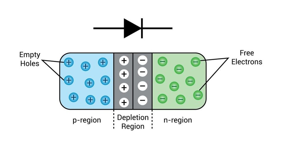
When a P-N junction is formed, a depletion region develops at the interface. This region is crucial for diode operation:
Formation: Electrons from the N-type material diffuse into the P-type material, while holes from the P-type material diffuse into the N-type material.
Charge Balance: The diffusion creates a buildup of negative charge in the P-type region and positive charge in the N-type region.
Electric Field: This charge imbalance generates an electric field across the depletion region.
Equilibrium: The electric field eventually prevents further diffusion, reaching a state of equilibrium.
The depletion region acts as an insulator, controlling current flow through the diode. Its width and characteristics are key to understanding diode behavior under different bias conditions. Diodes operate in two modes: forward bias and reverse bias.
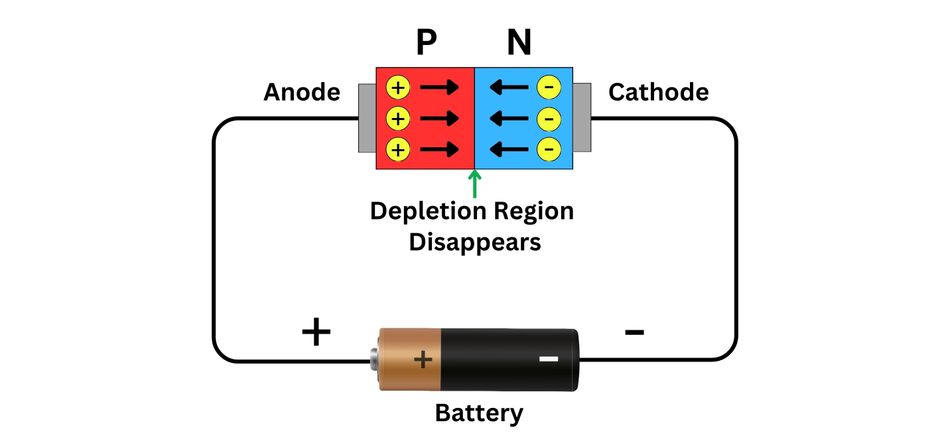
Forward Bias:
Positive voltage applied to anode, negative to cathode
Depletion region narrows
Potential barrier decreases
Electrons flow from cathode to anode
Holes flow from anode to cathode
Current flows through the diode
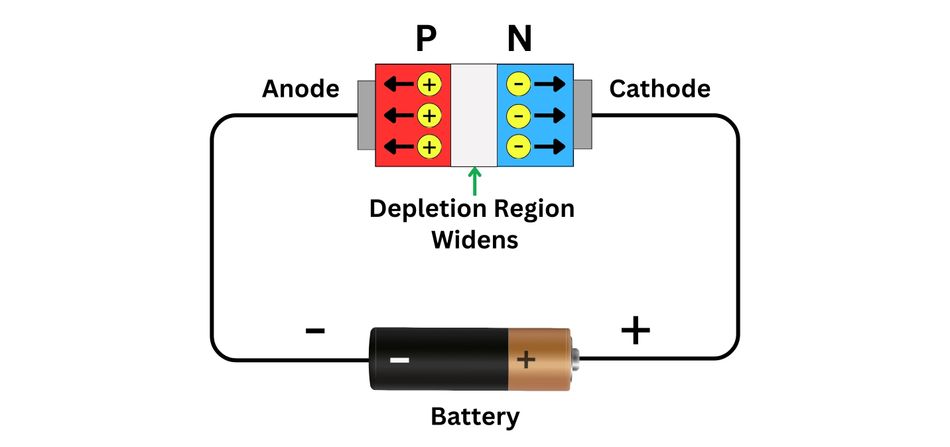
Reverse Bias:
Negative voltage applied to anode, positive to cathode
Depletion region widens
Potential barrier increases
Minimal current flow (only leakage current)
Diode blocks current in this direction
Stages of electron movement in a forward-biased diode:
Electron Injection: Cathode releases electrons into the conduction band
Diffusion: Electrons move through the N-type region towards the junction
Drift: Electrons cross the narrowed depletion region
Recombination: Electrons enter the P-type region and recombine with holes
External Current: Electrons flow through the external circuit back to the cathode
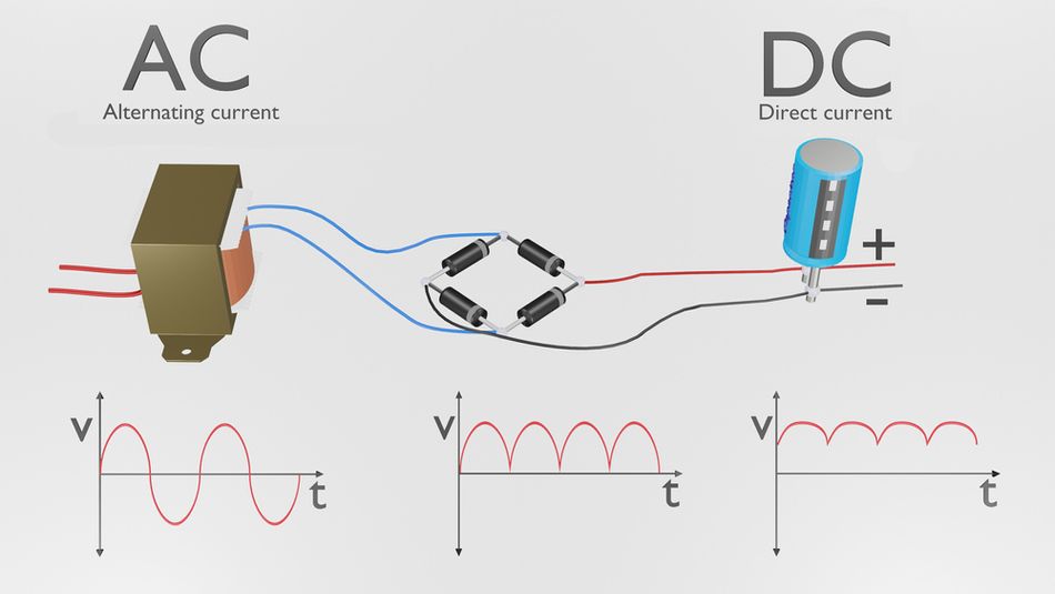
The forward and reverse bias characteristics of a diode are used in a variety of electronic circuits. For example, diodes can be used to convert alternating current (AC) to direct current (DC). This is done by connecting a diode in series with a load resistor. The diode allows current to flow through the resistor in one direction only, which creates a DC voltage across the resistor.
Diodes can also be used to protect electronic circuits from damage. For example, a diode can be connected in parallel with a load resistor to protect it from overvoltage. If the voltage across the load resistor becomes too high, the diode will conduct current and bypass the resistor, thereby protecting it from damage.
Diodes are essential components in a wide variety of electronic circuits. They are used to rectify AC to DC, protect circuits from overvoltage, and control the flow of current. From simple rectification to complex power supplies and chargers, diodes play a vital role. Diodes are available in a variety of different types, including silicon diodes, germanium diodes, and zener diodes.
Recommended Reading: Optimizing Diode Functionality: Forward and Reverse Bias
Diode Varieties: A Spectrum of Anode-Cathode Configurations
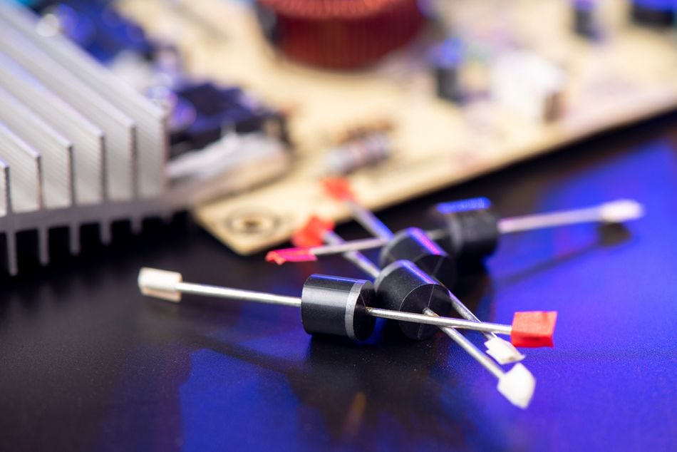
Rectifier Diodes: The Current-Controlling Classics
Rectifier diodes are fundamental components in electronic circuits, designed to convert alternating current (AC) to direct current (DC). These diodes feature a simple P-N junction structure, with the anode formed from P-type semiconductor material and the cathode from N-type material. The junction between these two regions creates the characteristic unidirectional current flow.
In rectifier diodes, the anode and cathode play distinct roles:
Anode: Acts as the positive terminal, accepting electrons from the external circuit when forward-biased. It is typically made of heavily doped P-type material to enhance conductivity.
Cathode: Serves as the negative terminal, supplying electrons to the circuit when forward-biased. It is usually composed of heavily doped N-type material to ensure efficient electron emission.
The interaction between these two regions allows rectifier diodes to conduct current efficiently in the forward direction while blocking it in the reverse direction. This makes them ideal for AC to DC-conversion.
There are several different types of rectifier diodes, each with its own unique characteristics:
Half-Wave Rectifier: A half-wave rectifier uses a single diode to convert AC to DC. It allows only one-half of the AC waveform to pass through, resulting in a pulsating DC output. [3]
Full-Wave Rectifier: A full-wave rectifier uses two or four diodes to convert AC to DC. It allows both halves of the AC waveform to pass through, resulting in a smoother DC output.
Bridge Rectifier: A bridge rectifier is a type of full-wave rectifier that uses four diodes to convert AC to DC. It is more efficient than a full-wave rectifier that uses two diodes.
The following table compares different variants and types of rectifier diodes:
| Type | Forward Voltage Drop | Max. Forward Current | Reverse Recovery Time | Reverse Recovery Time |
| General Purpose (e.g., 1N4001) | 0.7-1.0V | 1A | 30µs | Low Power Rectification |
| Fast Recovery (e.g., UF4007) | 0.8-1.0V | 1A | 50ns | Switching Power Supplies |
| Schottky (e.g., 1N5819) | 0.2-0.4V | 1A | <10ns | High-Frequency Rectification |
| High-Power (e.g., 40EPF) | 0.7-1.0V | 40A | 25µs | Industrial Power Supplies |
| Ultrafast (e.g., MURS320) | 1.0-1.2V | 3A | 25ns | High-Frequency Inverters |
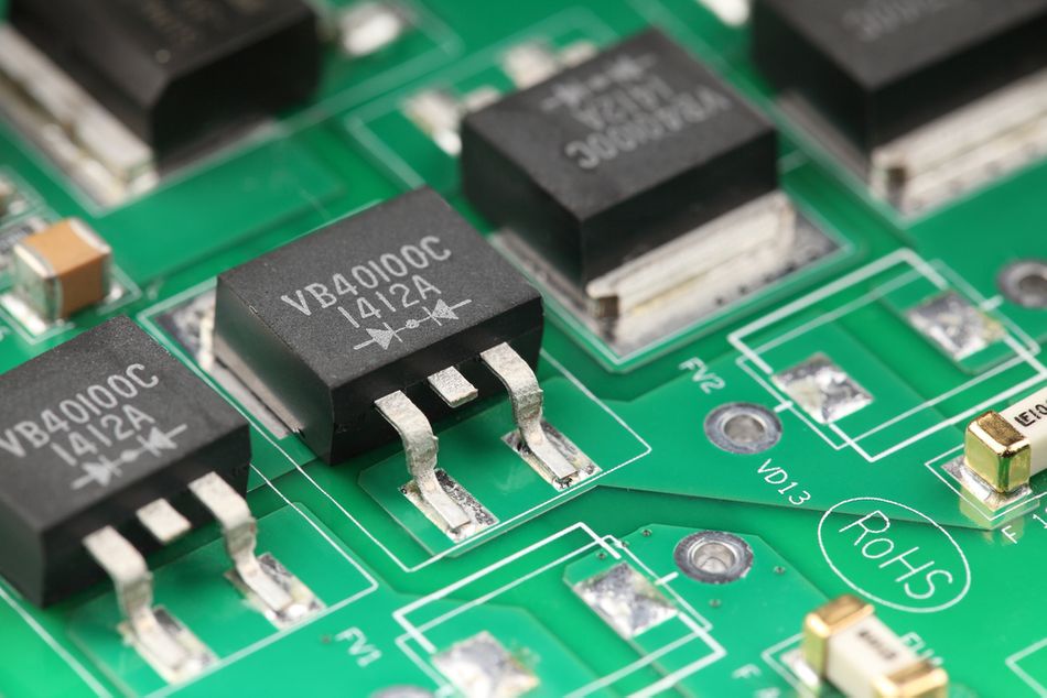
Rectifier diodes are used in a wide variety of electronic circuits, including power supplies, rectifiers, and amplifiers. They are also used in many household appliances, such as televisions, radios, and computers.
Let's explore some key areas where diodes play crucial roles:
Power Supplies: Rectifier diodes are used in power supplies to convert AC power from the main supply to DC power for electronic devices. [4]
Bridge Rectifiers: These configurations of four diodes efficiently convert AC to pulsating DC, forming the foundation of most power supplies.
Voltage Clamping: Diodes, particularly Zener diodes, can be employed to prevent excessive voltage spikes from damaging sensitive components.
Reverse Polarity Protection: By connecting a diode in series with a circuit, accidental reverse voltage connection can be prevented.
Signal Demodulation: Diodes are essential in demodulating amplitude-modulated (AM) radio signals, recovering the original audio information.
Each type of rectifier diode possesses unique characteristics suited to specific applications. This versatility enables engineers to optimize circuit performance based on factors such as voltage drop, current handling capacity, and switching speed.
Recommended Reading: Rectifier Diode: Revolutionizing Electrical Applications with Advanced Semiconductor Technology
Light-Emitting Diodes (LEDs): Illuminating Anode-Cathode Interactions
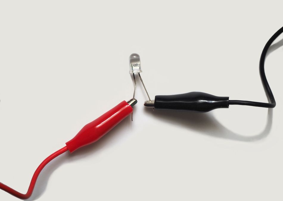
Light-emitting diodes (LEDs) are semiconductor devices that convert electrical energy into light energy. They are made of a semiconductor material, such as gallium arsenide phosphide (GaAsP), that emits light when an electric current passes through it. LEDs represent a specialized class of diodes designed to emit light when forward-biased. The anode-cathode configuration in LEDs is optimized for this unique purpose, differing significantly from standard rectifier diodes.
In LEDs, the anode and cathode are constructed from carefully selected semiconductor materials to facilitate light emission. The anode is typically made from a p-type semiconductor, while the cathode is composed of an n-type semiconductor. The junction between these two regions, known as the active region, is where the light-emitting process occurs.
When an LED is forward-biased, electrons from the cathode and holes from the anode are injected into the active region. As these charge carriers recombine, they release energy in the form of photons, resulting in light emission. This process, known as electroluminescence, is the fundamental principle behind LED operation.
The wavelength (and thus color) of the emitted light depends on the band gap energy of the semiconductor materials used in the anode and cathode. Various LED types and their corresponding anode-cathode materials include:
Red LEDs: Aluminum Gallium Arsenide (AlGaAs)
Green LEDs: Indium Gallium Nitride (InGaN)
Blue LEDs: Silicon Carbide (SiC) or Gallium Nitride (GaN)
White LEDs: Blue LED with yellow phosphor coating
Infrared LEDs: Gallium Arsenide (GaAs)
When an electric current passes through an LED, electrons flow from the cathode to the anode. The electrons recombine with holes in the semiconductor material, releasing energy in the form of photons. The photons are emitted as light, which is visible to the human eye.
The anode and cathode of an LED are connected to the positive and negative terminals of a power source, respectively. When the power is turned on, an electric current flows through the LED, causing it to emit light.
LEDs are used in a wide variety of applications, including lighting, displays, and electronic devices:
Lighting: LEDs are used in a variety of lighting applications, including home lighting, commercial lighting, and automotive lighting. They are more energy-efficient than traditional incandescent and fluorescent lights.
Displays: LEDs are used in a variety of display applications, including televisions, computer monitors, and digital signage. They offer a wide color gamut and high contrast ratio.
Electronic Devices: LEDs are used in a variety of electronic devices, including remote controls, cameras, and mobile phones. They are used for backlighting, indicators, and other purposes.
LEDs are becoming increasingly popular due to their energy efficiency, long life, and environmental friendliness. They are a versatile and efficient source of light that is used in a wide variety of applications.
Zener Diodes: Voltage Regulation through Specialized Cathodes
Zener diodes are specialized diodes designed to operate in the reverse breakdown region. They are named after Clarence Zener, who first described the phenomenon of voltage breakdown in semiconductors. These diodes exhibit distinctive properties that make them invaluable for voltage regulation applications. The key to their functionality lies in their specialized cathode design, which enables controlled and stable breakdown at a specific voltage.
The cathode of a Zener diode is heavily doped with impurities, creating a narrow depletion region. This design allows for a predictable and sharp breakdown voltage, known as the Zener voltage. When reverse-biased beyond this voltage, the Zener diode maintains a nearly constant voltage across its terminals, even as the current through it varies.
This specialized cathode enables voltage regulation through a process called Zener breakdown. Unlike avalanche breakdown in regular diodes, Zener breakdown occurs due to quantum tunneling effects. Electrons in the valence band of the semiconductor gain enough energy to tunnel directly into the conduction band, creating a stable current flow without damaging the device. [5]
The voltage-current characteristics of Zener diodes can be represented by the following graph:
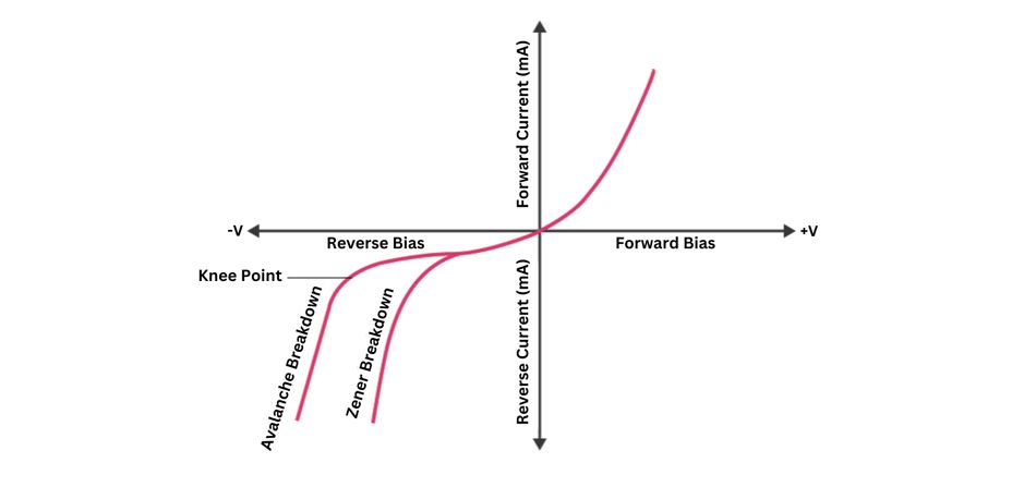
The V-I characteristics of a Zener diode can be divided into two parts as follows:
Forward Region: The forward characteristics of a Zener diode closely resemble those of a standard PN junction diode. The first quadrant of the above V-I graph shows a similar exponential increase in current with the rise in forward voltage.
Reverse Region: Zener diode initially conducts a low leakage current until its breakdown voltage (Zener voltage) is reached. Beyond this point, the diode enters a breakdown region, exhibiting a sharp current increase and maintaining a relatively constant voltage across its terminals.
Some commonly used specifications for Zener diodes are as follows:
Zener/Breakdown Voltage: The Zener or the reverse breakdown voltage ranges from 2.4 V to 200 V; sometimes, it can go up to 1 kV, while the maximum for the surface-mounted device is 47 V.
Current Iz (max): It is the maximum current at the rated Zener Voltage (Vz, 200μA to 200 A)
Current Iz (min): It is the minimum value of current required for the diode to break down.
Power Rating: It denotes the maximum power the Zener diode can dissipate. It is given by the product of the voltage of the diode and the current flowing through it.
Temperature Stability: Diodes around 5 V have the best stability
Voltage Tolerance: It is typically ±5%
Zener Resistance (Rz): It is the resistance to the Zener diode exhibits.
Zener diodes find widespread applications in electronic integrated circuits, including:
Voltage References: Providing stable reference voltages for analog-to-digital converters and precision measurement systems
Overvoltage Protection: Clamping voltages to protect sensitive components from voltage spikes, preventing circuit damage and ensuring system reliability.
Voltage Regulators: Maintaining constant output voltages in power supplies, ensuring stable operation of electronic devices and systems.
Level Shifting: Translating voltage levels between different parts of a circuit, enabling compatibility and proper operation of various components.
Waveform Clipping: Shaping signals in audio and RF applications, improving signal quality and reducing distortion.
The unique voltage-current relationship allows Zener diodes to maintain a stable voltage across a wide range of currents in the reverse breakdown region. This makes them ideal for voltage regulation and several other applications.
Recommended Reading: Zener Diode: A Comprehensive Guide to Its Principles and Applications
Anode-Cathode Dynamics: Performance Metrics and Characteristics
The performance of diodes is largely determined by the intricate interplay between their anodes and cathodes. Understanding the key performance parameters and characteristics of these components is crucial for engineers designing and optimizing diode-based circuits.
The current-voltage (I-V) characteristic curve is a fundamental representation of the electrical behavior of a diode. This curve illustrates the relationship between the current flowing through the diode and the voltage applied across it, providing crucial insights into the device's performance.

Several critical performance metrics define diode behaviour:
Forward Voltage Drop: This is the voltage across the diode when it's conducting in the forward direction. It's typically 0.6-0.7V for silicon diodes and 0.2-0.3V for Schottky diodes. The forward voltage drop affects power dissipation and efficiency in applications like rectifiers and LED drivers.
Reverse Breakdown Voltage: This is the voltage at which the diode starts conducting significantly in the reverse direction. It's crucial for determining the maximum operating voltage in applications like voltage regulators and protection circuits.
Forward Current: The maximum current the diode can handle in the forward direction. This parameter is essential for power handling capabilities in applications such as high-current rectifiers.
Reverse Leakage Current: The small current that flows when the diode is reverse-biased below the breakdown voltage. It affects the performance of sensitive analogue circuits and the efficiency of power supplies.
Junction Capacitance: The capacitance of the depletion region, which impacts the diode's high-frequency performance. It's particularly important in RF and high-speed switching applications.
These parameters significantly influence diode performance across various applications. For instance, in power supplies, a lower forward voltage drop reduces power loss, while a higher breakdown voltage allows for operation at higher voltages. In high-frequency applications, minimizing junction capacitance is crucial for maintaining switching speed and reducing signal distortion.
Key anode-cathode characteristics include:
Doping Concentration: The concentration of impurities added to the semiconductor material determines the electrical conductivity of the anode and cathode regions. Higher doping levels reduce the width of the depletion region, impacting the forward voltage drop and the reverse breakdown voltage.
Junction Area: The area where the anode and cathode meet, known as the junction, directly affects the diode's current handling capability. Larger junction areas can support higher currents but may also increase junction capacitance, affecting switching speed.
Material Bandgap: The energy bandgap of the semiconductor material dictates the voltage threshold for current flow. Materials with a wider bandgap, like silicon carbide, allow for higher reverse breakdown voltages, making them suitable for high-power applications.
Temperature Coefficient: This characteristic describes how the diode's electrical properties change with temperature. For instance, the forward voltage typically decreases with increasing temperature, while the reverse saturation current increases, which can affect the diode's performance in temperature-sensitive applications.
Switching Speed: The rate at which the diode can transition between conducting and non-conducting states is crucial in high-frequency applications. This speed is influenced by factors like junction capacitance and carrier recombination rates.
Noise Characteristics: Diodes can generate noise due to random carrier movements across the junction, especially in low-current or high-frequency applications. Minimizing noise is essential for precision electronic circuits.
The behavior of diodes can be described by several important equations:
1. Shockley Diode Equation:
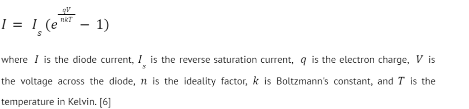
This equation models the current through a diode as a function of the voltage applied across it, taking into account the thermal energy and material properties.
2. Reverse Breakdown Voltage:
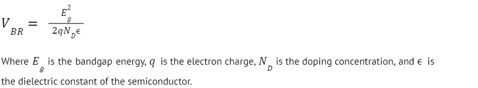
This equation describes the voltage at which a diode begins to conduct in reverse, leading to breakdown. It's critical for designing diodes that must withstand high reverse voltages.
3. Junction Capacitance:
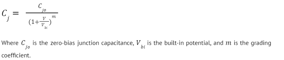
This equation models the capacitance of the diode's junction as a function of the applied voltage, influencing the diode's switching speed and frequency response.
The anode-cathode dynamics of a diode are complex and depend on a number of factors, including the materials used to make the diode, the doping levels of those materials, and the operating conditions of the diode. However, by understanding the basic principles of diode operation, it is possible to select the right diode for a given application.
Recommended Reading: How Does a Diode Work: Unraveling the Heart of Electronic Control
Conclusion
Diodes, characterized by their unique anode and cathode terminals, are fundamental building blocks in electronics. Their interaction within the P-N junction enables a range of functionalities essential to modern technology. Understanding their behavior, often represented by the standard schematic symbol with an arrow indicating current direction, is crucial. These components interact with other circuit elements, such as capacitors, transistors, and resistors (measured in ohms), to perform diverse functions. From rectification and voltage regulation to optoelectronics and advanced circuit design, diodes continue to be indispensable components. As technology evolves, understanding the intricacies of anode-cathode dynamics will remain crucial for developing innovative electronic solutions.
Frequently Asked Questions (FAQs)
Q: What is the main difference between the anode and cathode in a diode?
A: The anode is the positive terminal, typically made of P-type semiconductor material, while the cathode is the negative terminal, usually made of N-type material. In forward bias, current flows from the anode to the cathode.
Q: What role do anodes and cathodes play in LED colour emission?
A: The colour of light emitted by an LED is determined by the bandgap energy of the semiconductor materials used for the anode and cathode. Different material combinations result in different photon energies and, thus different colours of emitted light.
Q: How do Zener diodes utilize their anode-cathode structure for voltage regulation?
A: Zener diodes have a heavily doped P-N junction that allows for a controlled breakdown at a specific reverse voltage. This breakdown occurs in the depletion region between the anode and cathode, enabling the diode to maintain a constant voltage across a wide range of currents.
Q: How does temperature affect the anode-cathode characteristics of a diode?
A: Temperature changes can significantly impact diode behavior. As temperature increases, the forward voltage drop typically decreases, while the reverse leakage current increases. This temperature dependence is described by the Shockley diode equation and is an important consideration in circuit design.
Q. What advancements in anode-cathode technology are driving improvements in diode performance?
A: Recent advancements include the development of wide-bandgap semiconductors like Silicon Carbide (SiC) and Gallium Nitride (GaN) for power diodes, enabling higher breakdown voltages and faster switching speeds. In optoelectronics, novel quantum dots and perovskite materials are being explored for more efficient and tunable LEDs and photodiodes.
References
[1] Wevolver. N-Type Vs P-Type: Difference Between P-Type and N-Type Semiconductors [Cited 2024 August 16] Available at: Link
[2] IOPscience. Gallium Arsenide and Gallium Nitride Semiconductors for Power and Optoelectronics Devices Applications [Cited 2024 August 16] Available at: Link
[3] Analog. Half-Wave Rectification [Cited 2024 August 16] Available at: Link
[4] Build-electronic-circuits. Rectifier Diode: Guide to Functionality and Circuits [Cited 2024 August 16] Available at: Link
[5] RS Components. A Complete Guide to Zener Diodes [Cited 2024 August 16] Available at: Link
[6] PV education. Ideal Diode Equation [Cited 2024 August 16] Available at: Link
Table of Contents
IntroductionThe Anatomy of a Diode: Anode and Cathode UnveiledThe Anode: Positive PowerhouseThe Cathode: Electron Acceptor ExtraordinaireThe Dance of Electrons: How Anodes and Cathodes InteractDiode Varieties: A Spectrum of Anode-Cathode ConfigurationsRectifier Diodes: The Current-Controlling ClassicsLight-Emitting Diodes (LEDs): Illuminating Anode-Cathode InteractionsZener Diodes: Voltage Regulation through Specialized CathodesAnode-Cathode Dynamics: Performance Metrics and CharacteristicsConclusionFrequently Asked Questions (FAQs)References