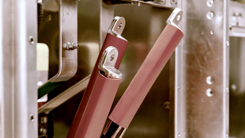
Heat Shrink Cable Accessories for Harsh Environments: Principles, Design, Manufacturing, and Applications
Article #6 of Connectivity and Sensing in Harsh Environments series: Heat shrink accessories offer a convenient way to protect elements of electrical power systems in harsh environments.
This is the final article in a 6-part series featuring topics on Connectivity and Sensing in Harsh Environments. The series will showcase how highly engineered connectivity, and sensing solutions enable advancements in manufacturing, transportation, construction, healthcare, energy generation, and consumer products. This series is sponsored by Mouser Electronics. Through the sponsorship, Mouser Electronics shares its passion for technologies that enable smarter and connected applications.
More than 40 years ago, cross-linked polyethylene (XLPE) cables started replacing oil-impregnated paper cables in low voltage (LV) and medium voltage (MV) distribution networks. In parallel to this change in the cable network, heat shrink cable accessories were introduced to the market and were an ideal solution for both joining and terminating paper and polymeric cable technologies.
This final article of the series covers heat shrink cable accessories in depth. In the first section, we introduce our readers to the concept of technology and go on to explain the principles and manufacturing processes involved in their making. We also explain how different elements and treatments can mold heat shrink tubings for different application scenarios. Finally, we provide an overview of some special heat shrink tubings by TE connectivity used in extremely harsh environments that require resilience against oil, fire, and nuclear radiation.
Introduction to Heat-Shrink Technology
Heat shrink tubings are used in electrical systems that offer sealing, insulation, strain relief, and even identification to the wires and connections they are applied on. On a small scale, these tubes can be put directly on the cables by sliding them over. When they are at the desired place, they are heated, the extent of which depends on the type of material, and the form factor of the heat-shrink tubing used. After heating, the tubing contracts hardens up and stays in the same conditions for a long period of time (for several years or decades).
When the technology was introduced initially, the majority of applications were for typical settings, such as the connection of standard cables and terminations, but utility and industrial needs went beyond everyday environments, such as:
Areas with a high Ultra Violet (UV) exposure
Heavy pollution areas
Salt Fog environments
Areas with oil leakage
Areas with inflammable entities
Areas with the presence of radioactive elements
The base material for the heat-shrink technology is polyethylene, one of the most commonly used plastics today. The chemical formula for polyethylene is (C₂H₄)ₙ where C₂H₄ is the repeating unit. The repeating units of polyethylene are subjected to cross-linking processes such as chemical or radiation cross-linking to form a molecular chain.
In a radiation cross-linking process, multi MeV electron accelerators are used, where electrons are accelerated to gain such high energies that they can initiate the cross-linking process (Fig 1). When this happens, hydrogen atoms are separated from the polyethylene chains, and the carbon elements between adjacent polymer chains establish a bond between the two polymer chains. With an increased cross-linking rate, the material usually gets more rigid.

Cross-linking effects in the materials cause them to lose their melting properties. They can now be heated to temperatures beyond the crystalline melting point without melting. Above this temperature, heat-shrink products such as extruded tubes or molded parts (breakouts and end caps) can be expanded and put in shape so that they can remain in this position. In contrast, the temperature will decrease below the crystalline melting point again.
Suppose the products are heated up again beyond the crystalline melting point, which typically happens during the installation by a gas torch or hot air gun. In that case, the materials will shrink again to their original shape. This kind of memory effect remains for the entire lifetime of the product allowing for almost an unlimited shelf life for the products under specific storage and environmental conditions.
Material Modifications Grant Special Properties to Heat-Shrink Accessories
By using additives to the formulation, the characteristics of the tubes or molded parts can be modified. The chemical formulation is the key element to achieve specific and specialized features required for various industrial applications.
The following diagram shows a general overview of the different ingredients used to formulate heat shrink materials to gain the desired properties, depending on the final product.
Additive ingredient | Effects |
Iron Oxide | Pigment, UV screen, Anti-tracking |
Thermal Stabilizers | Thermal durability, long-term aging |
UV Stabilizers | UV absorption, long-term aging |
Oils | Filler acceptance, Dielectric strength, Viscosity modification |
Anti-tracking fillers | Anti-tracking, Flame retardant |
Process Aids | Dispersion, Process speed, Surface finish |
Carbon Blacks | Conductivity, UV screen, Reinforcement, Pigment |
Other Fillers | Cost reduction, UV screen, Reinforcement |
Table 1: Ingredients to formulate heat-shrink materials with the desired properties. Source: TE Connectivity
As a consequence, the formulation of a material can be pretty complex. Without adversely impacting each other, it needs to be ensured that the combination of all the different materials will combine functions including:
Mechanical properties
UV resistance for outdoor applications
Electrical properties
Oil blocking characteristics
Tracking and erosion
Radiation resistance
Flame retardant/fire resistance properties
Electrical stress control
Outdoor heat-shrink materials are used in different areas of the world with different UV radiation levels. The most challenging UV requirements might be found in desert environments where insulation materials are consistently subjected to high UV radiation. With increased elevation, UV radiation also increases. A typical value is that for every 500 m of altitude, the UV radiation increases by about 3.5 %.
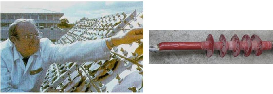
Test sites in desert areas are used to analyze different formulations to prove their long-term resilience to UV radiations(Fig. 2). For accelerated UV aging tests, UV lamb (Xenon) testing for lab simulation has become a standard. EMMAQUA® or Weather-Ometer® testing has also been used as an alternative to verify the properties.
Environments Demanding Specific Properties in Heat Shrink Accessories
Oil Blocking Characteristics for Heat Shrink Accessories
Environments, where oil-blocking characteristics are required, can be seen as a whole new class of harsh environments that bring new challenges for the heat shrink tubings. A typical application, in such a case, would be using a cable accessory in a joint or termination for oil-impregnated paper cables, either in a paper-to-paper cable connection or more common paper-to-polymeric cable joint, a so-called transition joint.
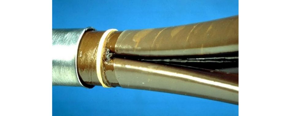
Without oil-blocking characteristics, the oil-impregnated paper cables suffer from the migration of the oil and dry out over time. As the oil with its good insulation characteristics plays a vital insulation role, its loss would constantly lead to the degradation of the cable's electrical insulation property, which could finally end up in a breakdown of the insulation and a failure of the cable accessory. This accessory usually needs to be maintained for a service life of 40 years. Maximum operating temperatures of the cable conductor can go up to 70°C.
Heat-shrink materials with oil-blocking characteristics can also be used in oil and gas or petrochemical industry applications, where such features are a must.
Flame-Retardant Heat Shrink Cable Accessories
Specific environments such as railway, offshore applications, government buildings, or power-plant applications require flame-retardant cables and cable accessories. Typical fire safety standards like IEC-60332[1] and IEEE-1202[2] need to be met by the cables. It has become a common practice and an industry understanding to make cables with cable accessories compliant with these standards to prove their suitability.
During the IEEE-1202 test, the cable or cable with an accessory is put on a flame. After 20 minutes, the flame is removed, and it is expected from the product that, due to its own characteristics, the flame will be extinguished. The damaged area or flame propagation caused by this test should be limited to 1.5 m.
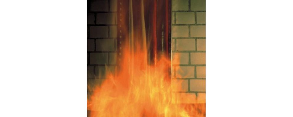
The right additive during formulation, combined with a particular wall thickness in the heat-shrink tube, will result in a flame-retardant heat-shrink tube.
Fire-Resistant Heat-Shrink Accessories
Beyond flame-retardance, specific industry requirements require fire resistance properties, where cable and accessories need to maintain system integrity up to 180 minutes. The requirement is much more stringent compared to fire retardance and requires a different design approach. Accessories are usually covered or combined with low-smoke zero-halogen (LSZH) materials for the benefits they offer. As the name suggests, LSZH materials emit low-smoke and almost no halogen gasses when exposed to fire. However, LSZH properties on their own will not bring the properties needed for heat-shrink cable accessories to achieve the system integrity for an extended period of time.
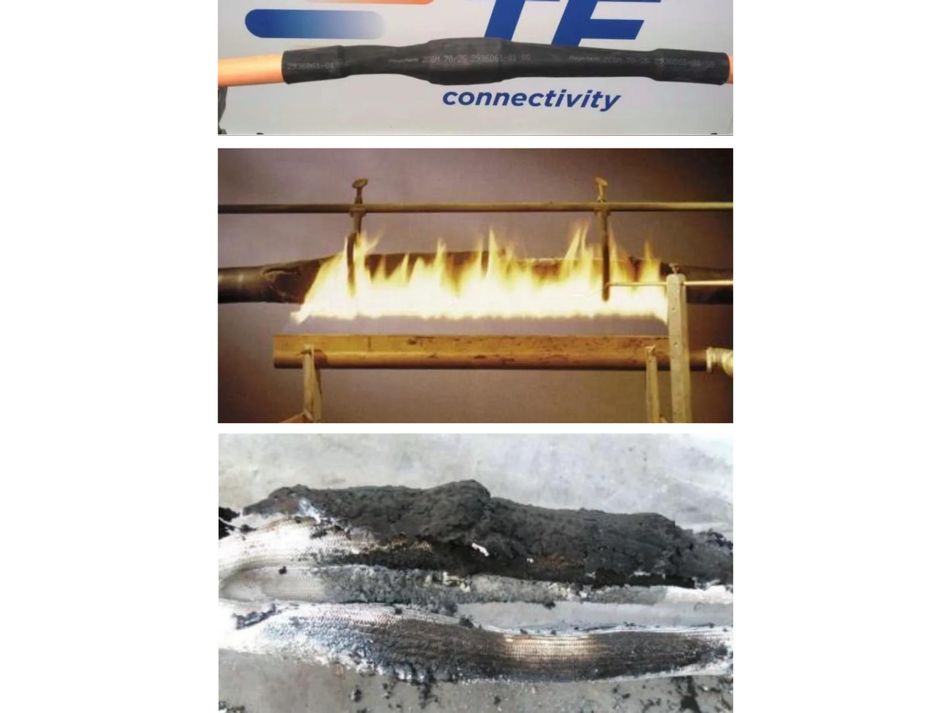
As a solution, the heat-shrink cable accessories are combined with additional protective layers acting as a barrier against the fire and preventing the flame from penetrating the inner insulation. IEC-60331 is the standard where test procedures for fire-resistant cable and cable accessories (Fig. 6) are defined.
Heat-Shrink Cable Accessories for Electrical Systems in Nuclear Reactors
One of the most severe environments for cable accessories is in the containment areas of nuclear power plants, which require electrical systems to function under accidental conditions such as loss of coolant accident (LOCA), which is among the most severe forms of failures in the nuclear reactor.
In case of an accident, cable accessories should support the functioning of the emergency functions, such as the emergency shutdown of the reactor, containment isolation, and prevention of the release of radioactive material by offering a 360° protection to the electrical systems.
A full LOCA qualification simulates the severe accident conditions and therefore has to cover the following elements:
Simulation of aging effects by thermal and gamma-radiation
Radiation exposure during the lifetime
Accident simulation with high radiation
Exposure to extreme temperature and pressure profiles during saturated steam conditions
Harsh chemical spray testing
The newest generations of nuclear power plants, such as AP1000 or the European Pressurized Water Reactor (EPR), are built for 60-year service life. Therefore, the qualification process's thermal aging was already chosen to simulate a 60-year lifetime at a constant temperature of 90°C, which typically represents the maximum conductor temperature in power cables.
Although the products installed in the containment area are subjected to nuclear radiation, 40/60 years of gamma radiation needs to be simulated. Also, high radiation can occur during the accident, which needs to be taken into account and tested during the qualification process. Typical values can exceed 200 Mrad of gamma radiation.
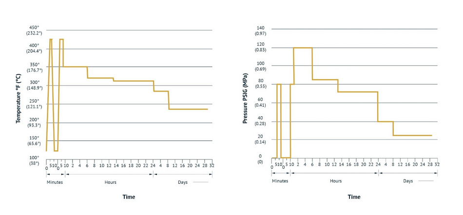
During the accident simulation, the heat-shrink cable accessories installed on cables will be taken into a vessel, where the temperature and pressure occurring during an accident will be simulated. A typical profile for a 30 days test on cable accessories is shown below, with maximum temperatures beyond 200°C and a maximum pressure beyond 0.8 MPa over normal environmental pressure.
Heat Shrink accessories by TE Connectivity for reliability in the harshest environments
TE’s heat shrink technology is based on specially-formulated thermoplastic polymer materials, optimized for specialized applications. The heat shrink tubings are known for their high quality, reliability, and ability to withstand weathering processes like pollution and contamination, UV-light, salt fog, and other harsh environments.
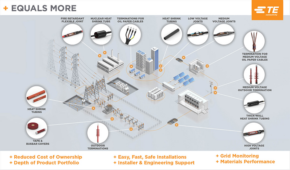
Sophisticated process controls employed during the manufacturing of TE’s heat shrink tapes, tubing, wraparound sleeves, splices, and terminations, ensure that the products maintain their shape memory off the shelf for decades, and perform robustly in the field for more than 40 years after installation. TE’s range heat shrink tubing and accessories are available on Mouser Electronics: Heat shrink and tubing by TE Connectivity | Mouser Electronics.
Conclusion
Heat-shrink cable accessories have been successfully applied in low-, medium-, and high-voltage networks. One of the challenging areas for their use in harsh environments with high UV radiation, heavy pollution, corrosive salt fog, and areas where oil barrier, flame retardant, or even fire-resistant properties are needed. Nuclear environments are also among the most challenging environments where heat shrink cable accessories are in use today and fulfill safety-related functions in accident conditions.
This article was initially published by Mouser and Amphenol in an e-magazine. It has been substantially edited by the Wevolver team and Electrical Engineer Ravi Y Rao. It was the final article of a 6-part series examining Connectivity and Sensing Technologies for Harsh Environments.
- The introductory article provided an overview of the different harsh environments that electronic circuits and systems are put through.
- The first article showcased how improvements in connectors, terminals, splices, relays, and heat shrink tubing enable connected applications
- The second article was focused on some key trends and design considerations for automotive connectivity systems.
- The third article presented three case studies on how connectors and terminals enable massive power handling in offshore installations.
- The fourth article shifted the focus back to the transport industry to explain the necessity of reliable connectors that withstand harsh environments.
- The fifth article was about the theory of sensor design for harsh environments.
- The final article examined the principles, design, manufacturing, and applications of heat shrink cable accessories in depth.
About the sponsor: Mouser Electronics
Mouser Electronics is a worldwide leading authorized distributor of semiconductors and electronic components for over 1,100 manufacturer brands. They specialize in the rapid introduction of new products and technologies for design engineers and buyers. Their extensive product offering includes semiconductors, interconnects, passives, and electromechanical components.
References:
[1] J. M. Daly, "IEEE 1202 flame testing of cables for use in cable tray," Conference Record of 1991 Annual Pulp and Paper Industry Technical Conference, 1991, pp. 100-104, doi: 10.1109/PAPCON.1991.239659.
[2] IEC 60332-1-2: Tests on electric and optical fibre cables under fire conditions, IEC, [Online], Available from: https://webstore.iec.ch/publication/22994
[3] ‘Heat shrink cable accessories: a 40 years proven technology for applications in harsh environments’, TE Connectivity, [Online], Available from:

