How Does a DC Motor Work? Unveiling the Power Behind Electric Motion
This article delves into the intricacies of DC motor operation, exploring the key components, core mechanisms, types, and their interactions to produce rotational motion.

26 Aug, 2024. 18 minutes read
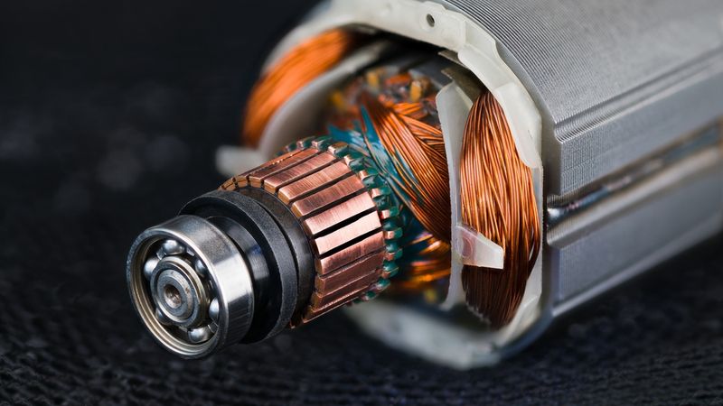
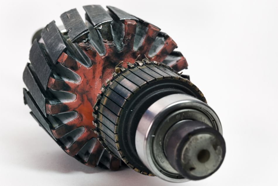
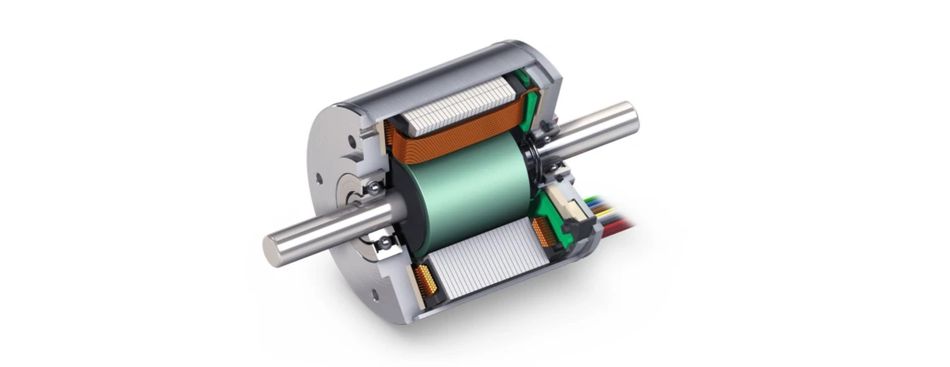
Rotor and Stator Detail of Electric DC Motor
Introduction
DC motors are the backbone of countless electrical devices, powering a vast array of machines that shape our daily lives. But how does a DC motor work? These versatile electromechanical devices convert electrical energy into rotational mechanical motion, driving everything from small household appliances to industrial machinery. From the precision movements of robotic arms to the comfort features of automobiles, DC motors are everywhere in our technological landscape.
In the automotive industry, DC motors control power windows and adjust seats, while in robotics, they enable precise movements and automation. Their efficiency, controllability, and compact size make them indispensable in fields ranging from aerospace to medical devices. This article delves into the mechanics and principles of DC motors, addressing the question, how does a DC motor work? By exploring the intricacies of its operation, we will uncover the essential role DC motors play in modern technology. Still curious about, how does a DC motor work? First, let’s get into the anatomy of a DC motor!
The Anatomy of a DC Motor: Building Blocks of Motion
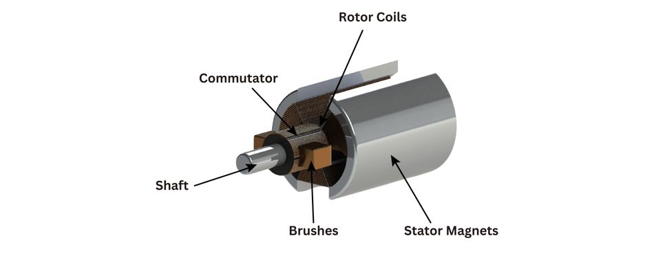
Understanding the inner workings of a DC motor requires familiarity with its key components. Each element plays a crucial role in converting electrical energy into mechanical motion. The main components of a DC motor are:
Stator: Stationary part of the motor, that houses the field magnets. These magnets can be permanent or electromagnets, creating a fixed magnetic field.
Rotor (Armature): Rotating part of the motor, typically consisting of wound wire coils. It generates a magnetic field that interacts with the stator's field to produce motion. [1]
Commutator: Cylindrical structure made of copper segments separated by insulating material. It reverses the direction of current flow in the rotor windings, ensuring that the rotor continues to rotate in the same direction.
Brushes: Stationary contacts, usually made of carbon, that maintain an electrical connection with the rotating commutator.
The stator provides the fixed magnetic field necessary for motor operation. The rotor, energized by electrical current, creates a second magnetic field that interacts with the stator's field, resulting in rotational force. The commutator and brushes work in collaboration to ensure that the current in the rotor windings is continuously reversed, maintaining the rotation of the motor. This ingenious arrangement of components allows for the continuous conversion of electrical energy into mechanical energy, powering countless devices in our modern world.
Magnetic Fields: The Invisible Force at Play
Magnetic fields are the fundamental force behind the operation of DC motors. These invisible lines of force permeate the space around magnets and electric currents. This creates a three-dimensional field that interacts with other magnetic materials and electric charges. In DC motors, magnetic fields play a central role in converting electrical energy into mechanical motion.
A magnetic field is a vector field, meaning it has both magnitude (strength) and direction. The direction of a magnetic field is typically represented by magnetic field lines. These lines are imaginary curves that trace the path of a magnetic force. The density of the lines indicates the strength of the magnetic field; the closer the lines are together, the stronger the field.
The stator of a DC motor creates a static magnetic field using either permanent magnets or electromagnets. There are two primary sources of magnetic fields:
Permanent Magnets, typically made from materials like neodymium or ferrite, produce a constant magnetic field without the need for electrical input.
Electromagnets, on the other hand, consist of wire coils wrapped around an iron core. When an electric current flows through these coils, it generates a magnetic field that can be controlled by varying the current.
The rotor, or armature, of the DC motor, also generates a magnetic field when an electric current passes through its windings. This field interacts with the stator's field, creating a force known as the Lorentz force. [2] It is a force that acts on a charged particle moving through a magnetic field. In a DC motor, the charged particles are the electrons flowing through the armature windings. The Lorentz force acts perpendicular to both the magnetic field and the direction of current flow, causing the rotor to rotate.

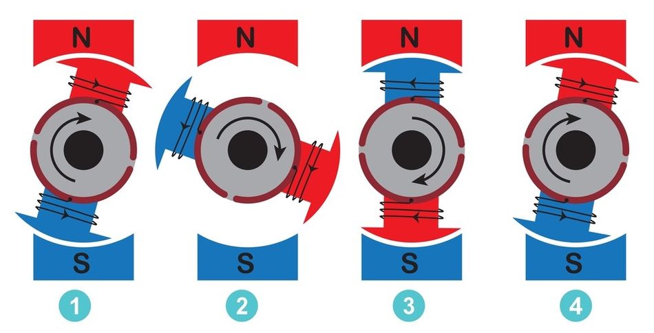
The interaction between the stator and rotor magnetic fields is dynamic and continuous. As the rotor turns, the orientation of its magnetic field changes relative to the stator's field. This changing relationship between the two fields maintains the rotational force, allowing the motor to continue spinning as long as electrical current is supplied.
The direction of the magnetic field produced by the stator can be reversed by adjusting the current flowing through its windings. This reversal of the magnetic field causes the rotor to rotate in the opposite direction. This principle is used to control the direction of rotation in DC motors.
Magnetic fields are the invisible force that drives the operation of DC motors. The interaction between the magnetic fields of the stator and rotor, facilitated by the commutator and brushes, produces the rotational motion that powers countless electrical machines. Understanding the principles of magnetic fields is essential for comprehending the mechanics of DC motors and their widespread applications.
Recommended Reading: What is Magnetism? Examples of Magnetic Substances
The Heart of the Motor: Understanding the Armature
The armature, also known as the rotor, is the central component of a DC motor that converts electrical energy into mechanical rotation. This cylindrical structure is mounted on bearings, allowing it to rotate freely within the motor's housing. The armature consists of a soft iron core with slots running along its length, providing a framework for the essential wire windings. [3]
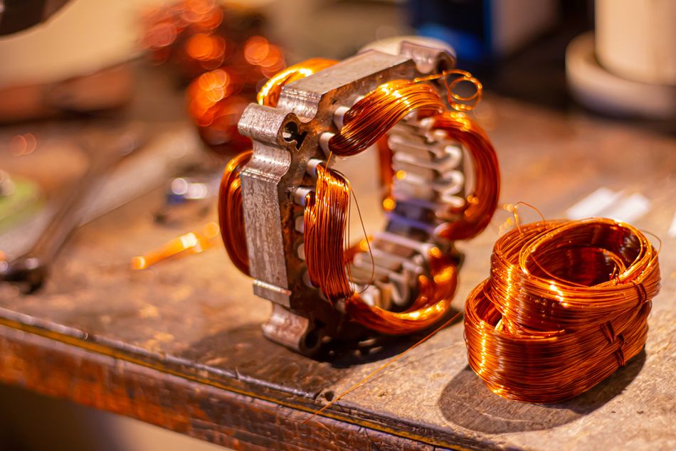
These coils of wire, typically made of copper, are wound around the armature core in a specific pattern. The winding process is crucial, as it determines the motor's performance characteristics. Coils are arranged in multiple loops and connected to form a continuous circuit. Each group of coils called a winding, is carefully positioned to interact with the motor's magnetic field at different points during rotation.
The importance of the armature in generating rotational force cannot be overstated. When an electric current flows through the armature windings, it creates a magnetic field around each coil. This field interacts with the static magnetic field produced by the stator (the stationary part of the motor). The interaction between these two magnetic fields creates a torque that causes the armature to rotate. As the armature turns, the commutator (a segmented ring connected to the windings) maintains the proper current direction in the coils, ensuring continuous rotation.
There are two main types of armatures used in DC motors:
Wound Armatures: In wound armatures, the windings are physically connected to the commutator segments. This type of armature is commonly used in larger DC motors.
Slotted Armatures: In slotted armatures, the windings are placed in slots within the armature core. This design allows for a more efficient use of space and can be used in both small and large motors.
The design of the armature has a significant impact on the performance, power output, efficiency, and speed characteristics of a DC motor. Factors such as the number of windings, wire gauge, and core material all play crucial roles in determining the motor's performance. Engineers carefully optimize these parameters to achieve the desired balance of torque, speed, and efficiency for specific applications.
The DC Motor in Action: From Electricity to Motion
DC motors transform electrical energy into mechanical motion through a series of electromagnetic interactions. The process occurs in a precise sequence, following the principles of electromagnetism to generate rotational force.
Current Flow through the Armature: When a DC power source is connected to the motor, electrical current flows through the armature windings via the brushes and commutator.
Magnetic Field Interaction: The current in the armature creates a magnetic field around the windings. This field interacts with the static magnetic field produced by the stator (either permanent magnets or electromagnets).
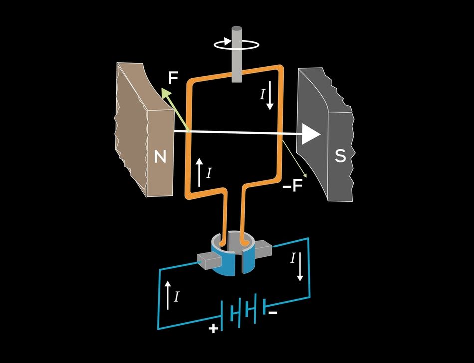
Rotational Force Generation: The interaction between the armature's magnetic field and the stator's field creates a force on the armature windings. This force is perpendicular to both the magnetic field and the direction of current flow, as described by Fleming's Left-Hand Rule.
Commutation Process: As the armature rotates, the commutator switches the direction of current flow in the windings at precise moments. This ensures that the magnetic field of the armature remains in the optimal position relative to the stator's field, maintaining continuous rotation.
Fleming's Left-Hand Rule plays a crucial role in understanding motor action. This rule states that if you extend the thumb, forefinger, and middle finger of your left hand at right angles to each other, they represent the direction of motion, magnetic field, and current, respectively. [4] In a DC motor, this rule helps predict the direction of the force acting on the armature conductors and, consequently, the direction of rotation. By applying this rule, engineers can design motors with specific rotational characteristics and optimize their performance for various applications.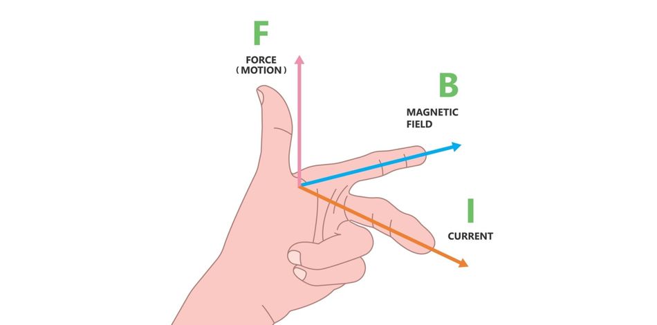
The interplay of these electromagnetic principles allows DC motors to convert electrical energy into useful mechanical work efficiently. Understanding these principles is essential for appreciating the versatility and efficiency of DC motors in various applications.
The Commutator-Brush System: Keeping the Motion Continuous
The commutator-brush system is a crucial component in DC motors, serving as the mechanical rectifier that enables continuous rotation. The commutator is a cylindrical structure mounted on the motor's armature shaft, consisting of multiple copper segments insulated from each other. These segments are connected to the armature windings. The brushes, typically made of carbon or graphite, are stationary components that maintain constant contact with the rotating commutator.

As the armature rotates, the brushes slide over the commutator segments, creating electrical connections that change dynamically. This sliding contact allows the brushes to deliver electrical current from the power source to the appropriate armature windings at precisely timed intervals. The key function of this system is to reverse the direction of current flow in the armature windings at specific points during rotation.
The reversal of current flow is essential for maintaining continuous rotation. As the armature turns, the magnetic field generated must constantly change orientation relative to the stator's magnetic field to produce consistent torque. The commutator-brush system achieves this by switching the polarity of the current in each armature winding as it passes through specific positions. This switching ensures that the magnetic force acting on the armature always pushes it in the same rotational direction.
The commutator-brush system is a critical component in maintaining a continuous rotation. Without it, the motor would simply oscillate back and forth instead of rotating continuously. The magnetic fields of the armature and stator always interact, ensuring a constant rotational force. This system enables DC motors to convert electrical energy into useful mechanical work efficiently and reliably.
However, the physical contact between brushes and commutator does introduce some limitations, such as wear over time and the potential for sparking. These factors have led to the development of BLDC motors for certain applications. Still, the traditional commutator-brush system remains widely used due to its simplicity, cost-effectiveness, and well-understood behaviour in numerous motor designs.
Induction motors, linear motors, and synchronous motors, for example, are all types of AC motors. AC motors can also include variable-frequency drives to control the motor's speed and torque, while DC motors are available in self-excited and separately excited-type models.
Recommended Reading: Motion Control in Robotics: 4 Types of Motors for Industrial Robots
Types of DC Motors: Tailoring Performance to Application
In a DC motor, a current-carrying conductor, typically the armature winding, interacts with a magnetic field to produce a force that drives the motor. The strength of this force is influenced by the EMF (electromotive force) induced in the conductor, which is directly related to the rate of change of magnetic flux cutting across the conductor. In many DC motor designs, a rotating magnetic field is generated by the stator. The interaction between this field and the current-carrying conductor in the rotor produces the necessary torque for rotation.
DC motors come in various configurations, each designed to meet specific performance requirements and operational needs. The four main types of DC motors are brushed DC motors, brushless DC motors, permanent magnet DC motors, and separately excited DC motors. Here are some of the most common types of DC motors:
| Motor Type | Commutation | Field Source | Field Source | Efficiency | Maintenance |
| Brushed DC | Mechanical (Brushes) | Permanent Magnet or Wound Field | Simple | Moderate | Regular |
| Brushless DC | Electronic | Permanent Magnet | Complex | High | Low |
| Permanent Magnet DC | Mechanical (Brushes) | Permanent Magnet | Simple | High | Moderate |
| Separately Excited DC | Mechanical (Brushes) | Separate Field Winding | Versatile | Moderate to High | Regular |
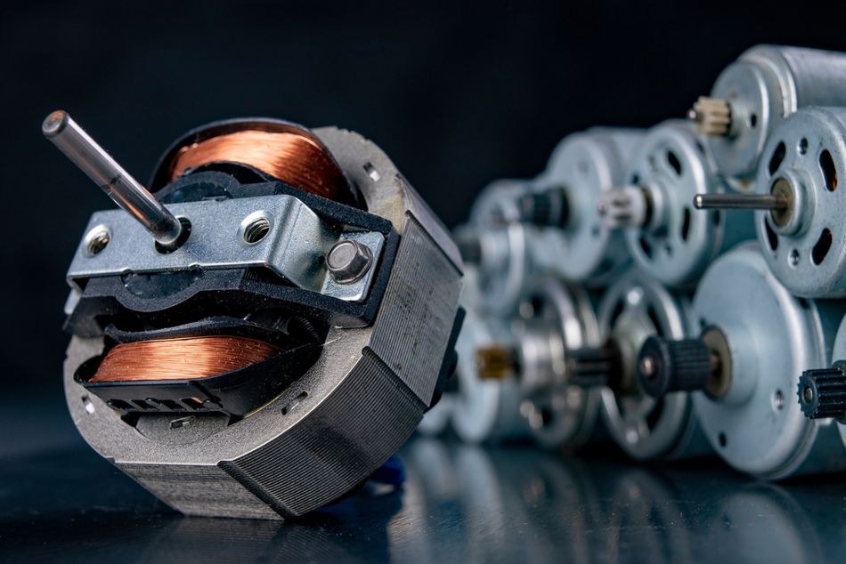
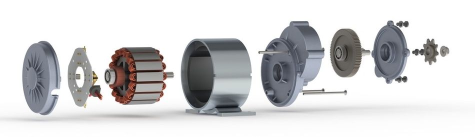
Brushed DC Motors are the most traditional type, offering simplicity and cost-effectiveness. They use a mechanical commutation system with brushes, making them easy to control but requiring periodic maintenance. [5] These motors are commonly used in automotive applications, power tools, and small appliances.
Brushless DC Motors eliminate the need for mechanical commutation by using electronic switching. This results in higher efficiency, lower maintenance, and longer lifespan. However, they require more complex control systems. Brushless motors are normally used in computer hard drives, electric vehicles, and high-precision industrial applications.
Permanent Magnet DC Motors use fixed magnets for their field, resulting in a compact design and high efficiency. They offer excellent speed control and are often used in applications requiring precise positioning, such as robotics, printers, and automotive power accessories.
Separately Excited DC Motors have independent field and armature windings, allowing for versatile speed and torque control. This makes them ideal for applications requiring a wide range of speeds or constant torque at various speeds. They are commonly used in industrial machinery, elevators, rolling mills, and electric vehicles.
Compound DC Motors combines the characteristics of both series-wound and shunt-wound motors. They have two sets of field windings: one connected in series with the armature winding (series field) and the other connected in parallel (shunt field). A compound motor is used in presses, shears, conveyors, hoists, rolling mills, heavy planners, etc.
Each type of DC motor has its own strengths and weaknesses, making them suitable for different applications. The choice of motor type depends on the specific requirements of the application. For example, a PM DC motor might be ideal for a small appliance due to its compact size and high efficiency. On the other hand, a series-wound DC motor might be better suited for a heavy-duty application that requires high starting torque.
Recommended Reading: DC Motor & DC Gear Motor Basics
Brushed DC Motors
Brushed DC motors, the older technology, use a mechanical commutation system. Current flows through brushes (typically made of carbon) that make contact with a rotating commutator. This design has been the backbone of DC motor technology for over a century due to its simplicity and cost-effectiveness.
Pros of Brushed DC Motors:
Simple Control Circuitry: Brushed DC motors are relatively easy to control, requiring only a simple power supply and a switch to reverse the direction of current flow.
Easy to Reverse Direction: Reversing the direction of a brushed DC motor is straightforward and can be achieved by simply reversing the polarity of the power supply.
High Starting Torque: Brushed DC motors are known for their high starting torque, making them suitable for applications that require quick acceleration.
Wide Speed Range: Brushed DC motors can operate over a wide range of speeds, providing flexibility in various applications.
Cons of Brushed DC Motors:
Regular Maintenance Required: The brushes in a brushed DC motor are subject to wear and tear over time. Regular maintenance, including brush replacement, is necessary to ensure optimal performance.
Limited Lifespan: The mechanical components of a brushed DC motor, such as the commutator and brushes, can wear out over time, limiting the motor's lifespan.
Potential for Electromagnetic Interference: The contact between the brushes and the commutator can generate sparks, which can lead to electromagnetic interference.
Lower Efficiency: Brushed DC motors generally have lower efficiency than brushless DC motors. This is due to the energy losses associated with the mechanical contact between the brushes and the commutator.
While brushed DC motors have been widely used for many years, their limitations have led to a growing preference for brushless DC motors in many applications. However, brushed DC motors still remain a viable option in certain situations, especially where simplicity and low cost are important considerations.
Brushless DC Motors
Brushless DC motors, in contrast, eliminate the need for physical commutation by using electronic commutation. They typically have a permanent magnet rotor and stationary armature windings. The position of the motor is detected by sensors, and the current is switched electronically to the appropriate windings.
Pros of Brushless DC Motors:
Higher Efficiency: Brushless DC motors offer higher efficiency compared to brushed DC motors. This is due to the reduced friction and electrical losses associated with the absence of mechanical contact between brushes and commutator.
Longer Lifespan: Without the mechanical wear and tear associated with brushes and commutators, brushless DC motors generally have a longer lifespan with minimal maintenance.
Better Heat Dissipation: The absence of brushes and commutators in brushless DC motors allows for better heat dissipation, improving motor reliability and performance.
Higher Speed Capability: Brushless DC motors can operate at higher speeds compared to brushed DC motors, making them suitable for applications that require high rotational speeds.
Quieter Operation: The absence of mechanical contact and reduced friction in brushless DC motors results in quieter operation compared to brushed DC motors.
Cons of Brushless DC Motors:
More Complex and Expensive Control Circuitry: Controlling a brushless DC motor requires more sophisticated control algorithms and circuitry compared to a brushed DC motor. This increases the initial cost and complexity.
Higher Initial Cost: Due to their advanced design and technology, brushless DC motors generally have a higher initial cost compared to brushed DC motors.
Requires Sophisticated Control Algorithms: Accurate control of a brushless DC motor requires sophisticated algorithms to ensure optimal performance and efficiency.
Potential for Demagnetization: In some cases, the permanent magnets used in brushless DC motors can experience demagnetization at high temperatures, potentially affecting the motor's performance.
The advantages offered by brushless DC motors have led to their increasing popularity in various applications. Their higher efficiency, longer lifespan, and improved performance make them a compelling choice for many industries. [7] Some of the key areas where brushless DC motors have gained traction include:
Automotive Industry: Electric vehicles and hybrid cars increasingly rely on brushless DC motors for traction and auxiliary systems.
Robotics: Brushless DC motors provide precise control and high power density, making them ideal for robotic applications.
Industrial Automation: Brushless DC motors offer improved efficiency and reliability in industrial machinery.
Consumer Electronics: Devices such as drones, power tools, and vacuum cleaners often employ brushless DC motors for their benefit.
While brushed motors still have their place in simple, cost-sensitive applications, the trend towards brushless technology is clear in high-performance and mission-critical systems. As control electronics become more affordable and compact, brushless motors are likely to continue gaining market share across a wider range of applications.
Recommended Reading: Stepper vs Servo Motors: What's the Difference?
DC Motor Performance: Factors Affecting Efficiency and Power
The performance of DC motors is characterized by several key parameters that collectively determine their efficiency and power output. Understanding these parameters and their interrelationships is crucial for optimizing motor selection and operation in various applications.
Torque is the rotational force produced by the motor, typically measured in Newton-meters (Nm). It represents the motor's ability to overcome resistance and accelerate a load. The torque output of a DC motor is directly proportional to the armature current and the strength of the magnetic field.
Speed, measured in revolutions per minute (RPM), indicates how fast the motor's shaft rotates. In DC motors, speed is inversely proportional to the load torque and directly proportional to the applied voltage. The no-load speed of a motor is determined by its voltage constant (Kv).
Power Output is the rate at which the motor can perform work, measured in watts. It is the product of torque and angular velocity (speed). The power output curve of a DC motor typically peaks at a specific operating point, where the motor delivers maximum power to the load.
Efficiency is the ratio of mechanical power output to electrical power input, expressed as a percentage. It represents how effectively the motor converts electrical energy into mechanical work. DC motor efficiency is influenced by various losses, including copper losses in the windings, iron losses in the core, and mechanical losses due to friction.
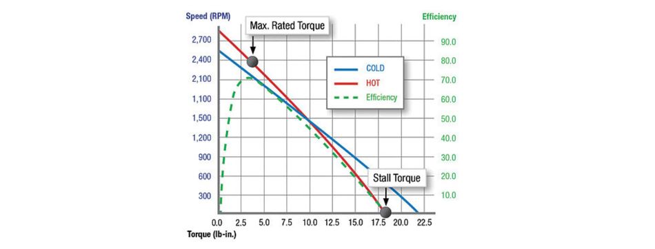
These parameters are intricately interrelated. As load increases, torque increases while speed decreases. This relationship is often represented by a torque-speed curve, which is characteristic of each motor type and size. The above graph of a typical torque-speed curve would be highly beneficial for visualising this relationship.
Several factors influence DC motor performance:
Load: The mechanical load on the motor directly affects its torque output and speed.
Voltage: Increasing the applied voltage generally increases motor speed and power output.
Current: The armature current determines the torque output and affects efficiency through copper losses.
Magnetic Field Strength: In motors with variable field strength, this affects both torque and speed characteristics.
Temperature: Motor performance can degrade at high temperatures due to increased resistance and potential demagnetization.
Commutation Quality: In brushed motors, the condition of brushes and commutator affects efficiency and overall performance.
Understanding these factors and their impacts allows engineers to select the appropriate motor for specific applications and operate them at optimal efficiency. For instance, in variable speed applications, controlling the voltage and current to maintain the motor at its peak efficiency point can significantly improve overall system performance.
Speed Control Techniques: Fine-Tuning Motor Operation
DC motors offer excellent speed control capabilities, which is one of their primary advantages in various applications. Three main techniques are commonly used to control the speed of DC motors: voltage control, Pulse Width Modulation (PWM), and field weakening. [6]
Voltage Control is the simplest method of speed control. The principle behind this technique is straightforward: by varying the applied voltage to the motor, the speed can be adjusted linearly. Increasing the voltage increases speed while decreasing it lowers speed. This method is simple to implement and cost-effective, making it suitable for basic applications. However, it has limitations. At lower speeds, the motor becomes less efficient, and there can be a significant drop in torque as the voltage is reduced.
Pulse Width Modulation (PWM) is a more precise approach to speed control. PWM controls the average voltage applied to the motor by varying the duty cycle of a digital signal. The motor receives full voltage for a brief period followed by a period of no voltage, effectively controlling the speed without losing torque. This method is more efficient than simple voltage control and maintains high torque at low speeds. However, it requires more complex electronic control circuits and can potentially introduce electrical noise and heating issues.
Field Weakening is a technique used primarily in separately excited DC motors. In this method, the field current is reduced, decreasing the magnetic field strength. This increases the speed of the motor beyond its normal rated speed. Field weakening allows for higher speeds beyond the rated limits and provides flexibility for variable-speed applications. However, it comes with significant limitations. As the field is weakened, the torque decreases substantially above the rated speed, and there's a risk of instability in motor operation.
Each of these methods has its place in motor control applications. The choice depends on factors such as the required speed range, torque characteristics, efficiency needs, and complexity of the control system. In many modern applications, a combination of these techniques may be used to achieve optimal performance across a wide range of operating conditions.
Recommended Reading: AC vs DC Motor: Unpacking Their Engineering Applications and Innovations
Conclusion
DC motors, a cornerstone of electromechanical energy conversion, remain indispensable in modern technology. The diversity of DC motor types, from brushed to brushless designs, offers engineers a variety of options to meet specific performance requirements. Understanding the principles behind DC motor operation is crucial for engineers seeking to optimize performance, select appropriate motor types, and integrate them effectively into their designs. As technology advances, the role of DC motors is likely to expand, offering new opportunities for innovation and improvement.
Frequently Asked Questions (FAQs)
Q: What are the main differences between DC and AC motors?
A: DC motors use direct current and typically offer easier speed control and higher starting torque. AC motors use alternating current, are generally more robust, and can be more efficient at constant speeds. DC motors often require less complex control circuits for variable speed applications.
Q: How can I improve the efficiency of a DC motor?
A: Efficiency can be improved by using high-quality materials for windings and magnets, optimizing the motor design to reduce losses, and implementing advanced control techniques like field-oriented control. It is necessary to ensure proper maintenance to minimize friction and electrical losses.
Q: How do I troubleshoot a DC motor that won't start?
A: Check the power supply and connections, inspect brushes and commutator for wear or damage, test for armature or field winding continuity, and verify that the load isn't excessive. Also, ensure the control circuit is functioning correctly and there are no mechanical obstructions.
Q: What factors should I consider when selecting a DC motor for my project?
A: Consider the required torque and speed range, power source availability, control requirements, environmental conditions, size and weight constraints, duty cycle, and expected lifespan. Also, evaluate whether a brushed or brushless design is more suitable for your application.
Q: How does regenerative braking work in DC motors?
A: In regenerative braking, the motor acts as a generator when decelerating. The kinetic energy of the system is converted back into electrical energy, which can be fed back into the power supply or dissipated through a resistor. This process provides braking force and can improve overall system efficiency.
References
[1] Gamak. What Is a Rotor? [Cited 2024 August 23] Available at: Link
[2] Global Spec. DC Motor Working Principle [Cited 2024 August 23] Available at: Link
[3] Carotron. Armature & Field Control of DC Motors [Cited 2024 August 23] Available at: Link
[4] Automate. Fleming's Left-Hand Rule: Electric Motor Theory Explained [Cited 2024 August 23] Available at: Link
[5] MPS. Brushless Vs Brushed DC Motors: When and Why to Choose One Over the Other [Cited 2024 August 23] Available at: Link
[6] ResearchGate. Speed Control of Series DC Motor Using PWM Technique: Pulse Width Modulated DC Motor Control [Cited 2024 August 23] Available at: Link
[7] Mosrac. What is a BLDC Motor? A Comprehensive Guide to Brushless DC Motors [Cited 2025 January 23] Available at: Link
Table of Contents
IntroductionThe Anatomy of a DC Motor: Building Blocks of MotionMagnetic Fields: The Invisible Force at PlayThe Heart of the Motor: Understanding the ArmatureThe DC Motor in Action: From Electricity to MotionThe Commutator-Brush System: Keeping the Motion ContinuousTypes of DC Motors: Tailoring Performance to ApplicationBrushed DC MotorsBrushless DC MotorsDC Motor Performance: Factors Affecting Efficiency and PowerSpeed Control Techniques: Fine-Tuning Motor OperationConclusionFrequently Asked Questions (FAQs)References