Next-generation MOSFET technology Meets Demand for Strong Thermal Performance in Automotive Applications.
Thermal system optimization is increasingly important as the power requirements of MOSFET applications increase.
Introduction
Power MOSFETs play a key role in a range of common high power applications with a particularly essential position in the automotive industry due to their fast switching speed, easy advanced paralleling capability, low gate drive power, wide bandwidth, ruggedness, ease of application, and relative ease of repair.
One often an under-discussed aspect of power MOSFETs is their thermal performance.
Thermal system optimization is increasingly important in relation to electrical optimization as the power requirements in their applications increase. Additionally, a MOSFETs strong thermal performance is essential for reliability.
Why is thermal important?
In power-electronic systems, temperature is one of the critical parameters because many properties of power semiconductors are temperature-dependent. For example, the lifetime of semiconductor components is strongly affected by temperature fluctuations due to loading. Each change in temperature causes mechanical stress in the component which affects solder and bond connections. In this type of scenario, the emphasis is not on the maximum or minimum temperature that the device can withstand but the temperature cycling or switching between temperatures that is most critical to reliability and performance.[1]
Applications for high power MOSFETs
Not all Power MOSFETs are suitable for the demanding power requirements of modern automotive design and cutting edge industrial applications. Only MOSFETs that can perform reliably under tough thermal conditions will be part of these developing industries.
The use of electronic control units (ECU’s) has increased in automotive applications as one method of reducing weight and increasing the efficiency of vehicles. A good example of this is in power steering which has transitioned from conventional oil pressure control to DC motors that use electronic control or electric power steering ECU’s.

Another application for power MOSFETs with strong thermal performance is in ABS braking systems. Anti-locking braking systems help vehicles maintain contact with the road surface and prevent skidding in conditions such as icy or wet roads. When the driver applies braking the ABS responds many times every second, to changes in the rotational speed of each wheel. Reducing or increasing brake pressure as necessary to maintain control. A pump motor is used to re-pressurize the systems when the ABS system operates. MOSFETs in this application must be reliable and rugged enough to withstand both the high external temperature of the vehicle itself as well as manage the switching load while maintaining thermal efficiency.
These examples, as well as other automotive applications such as DC/DC conversion and reverse battery protection, have fed the demand for improved performance of power MOSFETs used in the switching device in ECUs.
Outside of the automotive industry power MOSFETs with exceptional thermal performance are required for battery-powered power tools, power supply equipment, and telecom infrastructure.
Copper clip
All MOSFET designers face the same challenges of trying to reduce the MOSFET resistance, it's switching capability and also it's Electromagnetic Compatibility (EMC) to result in a MOSFET with very low resistance and very good switching performance while not producing any radiated electromagnetic interference.
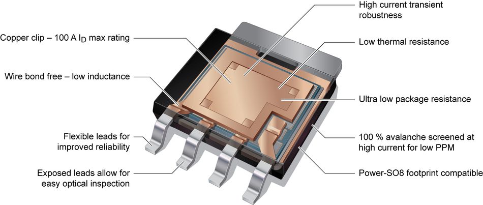
To meet the demand for high power with appropriate thermal properties MOSFET designers are rethinking traditional wirebond interconnects and moving towards copper clips for internal bonding. In clip-bonding technology, a solid copper bridge is attached to the die surface replacing multiple bonded wires.[2] Copper clip offers many advantages, which can offer significant improvements to MOSFET electrical and thermal properties, including increased maximum current capacity and excellent current diffusion, improved RDSon, low source inductance, and low thermal resistance (Rth).
Introducing LFPAK MOSFETs
In 2002, Nexperia teamed up with Hitachi to improve on the current power MOSFET solutions. From that cooperation came the LFPAK family of power MOSFETs. The LFPAK groups are a copper clip package that concretely addresses the limitations of previous MOSFET designs.
Let’s take a closer look at the physical design of the LFPAK. First, it has a very big source connection which provides a very low package resistance, it also has very short leads which help reduce the package resistance and inductance of the top clip. The new design has three source connections leads which greatly contribute to improving the current capability of the package. Previous DPAK designs were limited to 120 amps, but the smaller LFPAK is capable of as much as 300 amps.
Current spreading
In the LFPAK, the packaged resistance is improved by about 90 percent compared to the DPAK. From a current handling capability, it's not just about the maximum current the device can handle but about current spreading. With a typical internal wire-bonded package in a short circuit condition or a locked rotor condition, there will be a large inrush currents over short time periods so all the heat and current is crowding around the wire bonds resulting in very high current densities there and very little current density elsewhere in the device. This means local heating is created around the wire bonds and the full entitlement of the silicon is not gained in the application.
Compare this to the LFPAK - because it has the big source connection- the current spreads equally over the top surface of the device and get very good short-circuit handling capability is achieved compared to traditionally get with wire-bonded packages.

Leaded advantages
Nexperia is one of the suppliers that offer a copper clip leaded device. One of the key advantages of using a leaded device is the ability to use standard optical inspection equipment to examine the exposed leads. The solder joints are easily examined without needing expensive x-ray equipment and the top tabs solder joint is also easily inspected.
Another important aspect of the LFPAK design is that the exposed leads allow for wave soldering which can play a significant role in achieving reliability under stress. When a PC board goes through significant temperature cycles it will expand and contract and bend in response to the thermal conditions. In a scenario where a leadless package is fixed, with no flexibility in the lead, the repeated movements of the board can lead to the plastic at the join can crack posing a risk of contamination getting into the package or moisture ingress which can cause parametric shifts or even device failure.
In the instance of using the LFPAK or other leaded packages in the same demanding conditions, the leads act as a shock absorber for the movement. So as the PC board expands and contracts and bends, the leads expand and contract with it and absorb all of the flexing in the PC board. Trials of the LPAK have put the package through more than 2,000 temperature cycles and shown no degradation of the solder joint.
Thermal performance
One crucial area where the LFPAK differs from the DPAK family is its thermal performance. Smaller devices are preferred thanks to the space-saving they give, however, they also raise the valid concern about their thermal performance, and in applications where thermal performance is of primary importance, larger packages are generally chosen. However, the LFPAK family of MOSFETs demonstrates that high thermal performance is available in a small package.
A MOSFET in a fuel injection application in which thermal is a key element is a good example to examine this. In basic terms a fuel injection application is a MOSFET repetitively driving a solenoid load, switching it on and off. The timing and the clean turn on and turn off is of paramount importance. Because a solenoid is an inductive load, the turning off of the inductive load means the MOSFET is operating in avalanche mode. Avalanche mode refers to a considerable amount of current going through the MOSFET, hence why the thermal performance is key.
Thermal Simulation
RC thermal simulation of MOSFETs is an important tool for early design validation, allowing engineers to quickly check the device is suitable for the power and temperatures associated with the application. Currently, circuit simulators - which use mathematical models to replicate the behavior of an actual electronic device or circuit - are standard tools in the development and optimization of electronic systems. However, simulation has until now been limited to electronic functions because, in the simulation models available today, temperature dependence is generally limited to changing the static global temperature. Nexperia offers designers easy to use tools to better understand the thermal requirements and limits of their designs by providing the Foster RC Thermal models for all Power MOSFETs.
The LFPAK family
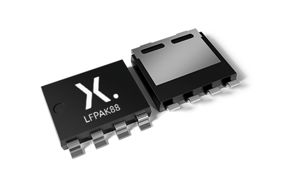
There are six products in the LFPAK portfolio. The LFPAK88 replaces the larger wire-bonded power packages such as D²PAK and D²PAK-7. It has an 8 x 8 mm footprint, - a physical footprint reduction of 60%, with a 64% lower profile.
The LFPAK88 copper-clip and solder die construction results in low electrical & thermal resistance, good current spreading, and heat dispersal. The maximum rating of 425 A and low RDS (on) of 0.7 mΩ in small package size, presents a power density of 48 times when compared to D²PAK devices.
Finally, the LFPAK88 offers unique low-stress gull-wing leads which create a rugged and thermally robust package and delivers reliability levels more than two times better than is required by the automotive standard AEC-Q101.

Conclusion
Power MOSFETs for automotive and industrial innovation need to offer a growing range of features including soft-start, live insertion, short-circuit resilience, avalanche ruggedness, and careful thermal management. Attention will be increasingly given to various thermal simulation models as the power density demands of these applications rises. MOSFET packages that can provide performance, reliability, and proven AEC-Q101 quality will play a key role in pushing innovation.
About the sponsor: Nexperia
Semiconductor manufacturer Nexperia is tackling the demand for strong thermally performing MOSFETs for the automotive industry. They are developing products that take advantage of copper clip technology to produce packages with very low resistance and solid switching performance while not producing any radiated electromagnetic interference.
The Nexperia LFPAK products such as the LFPAK88 are ready for use in the automotive industry and perform to AEC-Q101 standard qualification standards.
References
1. Thermal Modeling of Power-electronic Systems [Internet]. Munich: Fraunhofer; 2000. Available from: https://www.iisb.fraunhofer.de/content/dam/iisb2014/en/Documents/Research-Areas/Energy_Electronics/publications_patents_downloads/Publications/Therm_Modelling_2000_IISB.pdf
2. Copper Clip Package for high performance MOSFETs and its optimization [Internet]. Singapore: United Test and Assembly Center Ltd; 2016. Available from:https://www.utacgroup.com/wp-content/uploads/2019/09/Copper-Clip-Package-for-high-performance-MOSFETs.pdf


