Open Circuit vs Short Circuit: Core Differences between Open and Closed Circuit
Understanding the theoretical principles, real-life implementations, maintenance, and preventive measures for open and closed circuits and navigating the differences between open circuit vs short circuit

14 Aug, 2024. 17 minutes read
Introduction
In electrical engineering, knowledge of fundamental concepts of open circuits vs short circuits is crucial for designing safe and efficient systems. These two extreme conditions represent opposite ends of the circuit behavior spectrum. Each state has unique characteristics and implications. An open circuit refers to disruption in current flow while a short circuit refers to a continued low-resistance path for electrical current potentially leading to excessive current.
Understanding these simple yet highly critical concepts is a core requirement for circuit design, electrical testing, troubleshooting, and maintaining electrical safety. Therefore, engineers who can accurately identify and manage open and short circuits are better equipped to prevent system failures, avoid hazardous situations, and optimize performance. On the other hand, misidentifying or mishandling these conditions can result in equipment damage, electrical fires, or even personal injury.
Open Circuit vs Short Circuit: A Comprehensive Comparison
Defining the Extremes
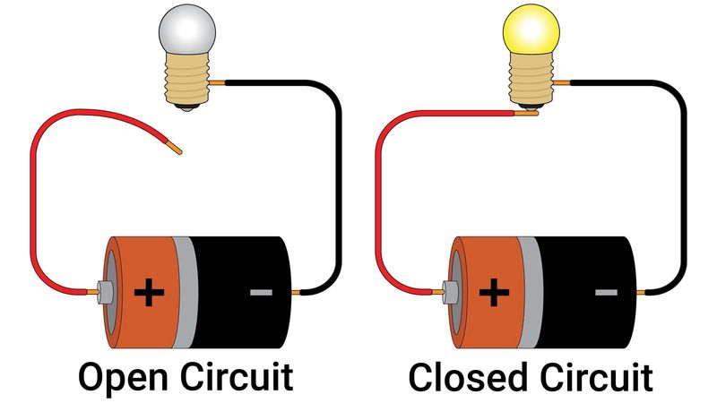
An open circuit is a break or disconnection in the electrical path, preventing current flow. This results in infinite resistance between two points in the circuit.
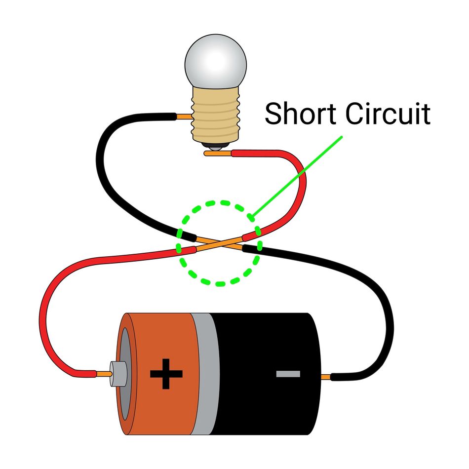
On the other hand, a short circuit is characterized by a direct connection between two points in a circuit with minimal or no resistance, leading to an excessive flow of current.
The open circuit vs short circuit comparison reveals fundamental differences in their characteristics and effects on electrical systems.
Broken wires, faulty switches, or disconnected components typically cause open circuits. They result in no current flow and maintain the full voltage potential across the open points.
Short circuits, conversely, can be caused by accidental connections, damaged insulation, or component failures. They lead to a sudden current surge and a dramatic voltage drop across the shorted points.
Recommended Reading: What is an Open Circuit: A Deep Dive for Engineers
The ability to identify and differentiate between open circuits and short circuits is essential for ensuring the safety, reliability, and efficiency of electrical equipment and infrastructure.
Electrical Behavior Analysis
In an open circuit, the electrical path is interrupted and there is no further conductive path for the current to travel. It results in an infinite resistance, causing zero current flow, as electrons cannot traverse the break in the circuit. The voltage across the open points remains at its full potential, equal to the source voltage. Consequently, there is no power dissipation in an ideal open circuit.
Conversely, a short circuit creates a path of negligible resistance between two points in a circuit. This minimal resistance allows for an extremely high current flow, limited only by the power source's capacity and the circuit's inherent resistance. The voltage drop across a short circuit approaches zero, as there is virtually no resistance to create a potential difference. The power dissipation in a short circuit can be enormous, often leading to rapid heating and potential damage to circuit components or the power source itself.
The extreme nature of these conditions becomes evident when analyzing their impact on circuit parameters:
Resistance | Current Flow | Voltage Drop | Power Dissipation | |
Open Circuit | Approaches infinity (∞ Ω) | I = V / R | Full source voltage | P = I^2 * R |
Short Circuit | Approaches zero (0 Ω) | I = V / R | Approaches 0 V | P = I^2 * R |
Impact on Circuit Components
Open circuits and short circuits can have severe consequences on various circuit components, often leading to malfunction or permanent damage. Understanding these effects is crucial for proper circuit design, maintenance, and troubleshooting.
Open circuits typically result from broken connections, faulty switches, or component failures that interrupt the current path. The impact on circuit components includes:
Resistors | Capacitors | Inductors | Semiconductors | |
Open Circuits |
|
|
|
|
Short Circuits |
|
|
|
|
Real-world examples of component failures due to open and short circuits include:
Burnt-out light bulbs: An open circuit in the filament prevents current flow, rendering the bulb inoperative.
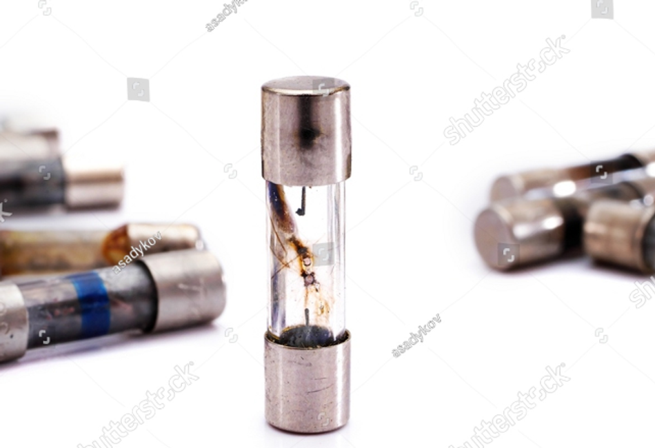
Blown fuses: Intentional open circuits created to protect against overcurrent conditions in short-circuit scenarios.
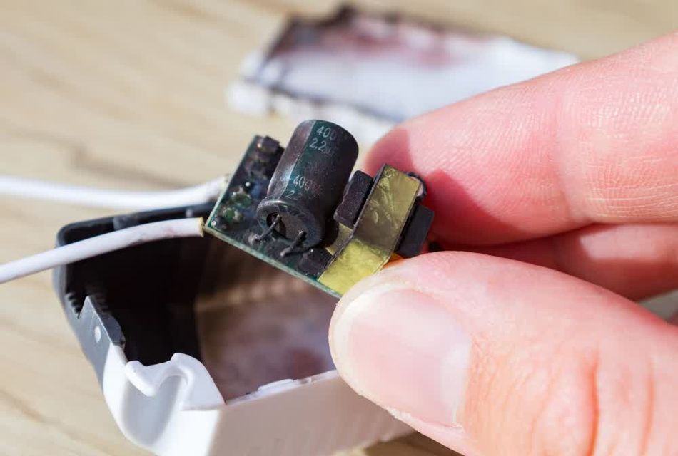
Melted power supply components: Short circuits in electronic devices can cause power supply components to overheat and melt, often accompanied by a distinct burning odor.
Failed motor windings: Short circuits between turns in motor windings can cause localized heating, leading to insulation breakdown and motor failure.
Suggested Reading: AC vs DC Motor: Unpacking Their Engineering Applications and InnovationsDamaged printed circuit boards (PCBs): Short circuits due to conductive contamination or manufacturing defects can cause tracks on PCBs to overheat and lift off the board.
Exploded electrolytic capacitors: Short circuits or reverse voltage conditions can cause electrolytic capacitors to heat up, build internal pressure, and rupture.
To summarize the key differences in the open circuit vs short circuit comparison, consider the following table:
Characteristic | Open Circuit | Short Circuit |
Resistance | Infinite | Near zero |
Current Flow | None | Excessive |
Voltage Drop | Full | Minimal |
Power Dissipation | None | Extreme |
Typical Causes | Broken wires, disconnected components | Damaged insulation, accidental connections |
Safety Concerns | System malfunction, no immediate danger | Overheating, fire hazard, component damage |
Contextual Study of Open and Short Circuits
Current Flow and Resistance
The movement of electric charge (current) is driven by a difference in electric potential, or voltage, measured in volts (V).
Resistance, measured in ohms (Ω), is the property of a material that opposes the flow of electric current. Materials with high resistance, like rubber or glass, are insulators, while those with low resistance, such as copper or gold, are conductors.
The relationship between current, voltage, and resistance is described by Ohm's Law: V = I * R, where V is voltage, I is current, and R is resistance. This fundamental law shows that:
Increasing voltage increases current (if the resistance remains constant).
Increasing resistance decreases current (if the voltage remains constant).
Current is inversely proportional to resistance (if the voltage remains constant).
Voltage and Power in Circuits
Voltage, current, and power are interconnected elements that define the behavior of electrical circuits. Voltage, measured in volts (V), represents the electrical potential difference between two points in a circuit. It acts as the driving force that pushes electric charges through a conductor, creating current. Current, measured in amperes (A), is the flow rate of electric charges through a circuit.
Power, measured in watts (W), quantifies the rate at which electrical energy is transferred or consumed in a circuit. The relationship between these three factors is expressed by the power equation:
P = V * I,
where P is power, V is voltage, and I is current. This equation demonstrates that power increases with either higher voltage or higher current.
In different circuit configurations, these factors interact in unique ways:
Series Circuits: Voltage is divided across components, while current remains constant. The total power consumed is the sum of power consumed by each component.
Parallel Circuits: Voltage remains constant across components, while current is divided. The total power consumed is still the sum of power consumed by each component.
Complex Circuits: A combination of series and parallel configurations where voltage and current distribution depends on the specific arrangement of components.
The following table compares voltage, current, and power characteristics in ideal circuits:
Circuit Type | Voltage | Current | Power |
Series | Divided across components | Constant | The sum of component powers |
Parallel | Constant across components | Divided among components | The sum of component powers |
Short Circuit | Very low (ideally zero) | Very high (limited by source) | Very high (potentially destructive) |
Open Circuit | Full source voltage | Zero | Zero |
In the context of open circuits and short circuits, these characteristics take on extreme values. In an open circuit, the voltage across the open point equals the full source voltage, but the current and power are zero due to the infinite resistance.
Conversely, in a short circuit, the voltage across the short is nearly zero, but the current can be extremely high, limited only by the power source's capacity and any residual resistance in the circuit. This can result in very high power dissipation, often leading to component damage or failure.
Open Circuits: The Path of Infinite Resistance
Characteristics and Causes
The defining feature of an open circuit is its infinite resistance, which effectively prevents any current from flowing through the circuit. This infinite resistance arises from a physical break or gap in the conductive path, creating an insurmountable barrier for electrons.
Key characteristics of open circuits include:
Infinite resistance between two points
Zero current flow
Full voltage potential across the open points
No power dissipation in the ideal case
Common causes of open circuits include:
Broken or disconnected wires
Faulty switches or relays
Blown fuses or tripped circuit breakers
Corroded or loose connections
Failed components (e.g., burnt-out resistors or capacitors)
Intentional design features (e.g., switches for circuit control)
Real-world examples of open circuit scenarios in various applications:
Lighting systems: A burnt-out light bulb creates an open circuit, preventing current flow and leaving the light non-functional.
Industrial control systems: A loose connection in a control panel can create an open circuit, causing machinery to stop functioning or safety systems to engage.
Consumer electronics: A cracked solder joint on a circuit board can create an intermittent open circuit, leading to unreliable device operation.
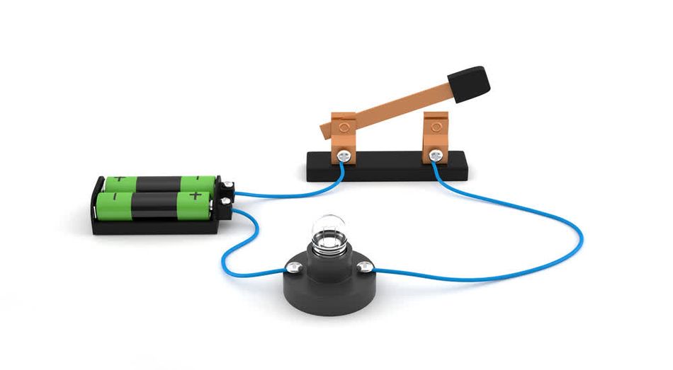
In this diagram, the open switch creates a break in the circuit, preventing current flow from the battery to the load. The voltage potential exists across the open switch, but no current can flow due to the infinite resistance at that point.
Consequences and Detection
When an open circuit occurs, it disrupts the flow of current and components in series with the open circuit receive no power, causing them to stop functioning.
The voltage distribution in an open circuit scenario is also affected. In a series circuit with an open, the entire supply voltage appears across the open points, while other components in the circuit experience no voltage drop. In parallel circuits, the open branch simply ceases to conduct current, potentially overloading other parallel paths.
Detecting open circuits is crucial for maintaining and troubleshooting electrical systems. Several methods can be employed:
Visual Inspection: Look for obvious signs of damage, such as broken wires or loose connections.
Continuity Testing: Use a multimeter set to continuity mode to check for breaks in conductivity.
Voltage Measurement: Measure voltage across suspected open points; full source voltage indicates an open circuit.
Current Measurement: Use an ammeter to detect the absence of current flow in a circuit branch.
Specialized equipment, particularly multimeters, plays a vital role in identifying open circuits. A digital multimeter can be used in various modes:
Continuity Mode: Emits a beep when a complete path is detected.
Resistance Mode: Measures resistance; an "OL" (overload) reading often indicates an open circuit.
Voltage Mode: Measures voltage across suspected open points.
Step-by-step guide for troubleshooting potential open circuit issues:
Safety First: Ensure the circuit is de-energized before testing unless voltage measurements are required.
Visual Inspection:
Examine wires, connections, and components for visible damage.
Check for loose connections or disconnected wires.
Continuity Testing:
Set the multimeter to continuity mode.
Test suspected open points; no beep indicates an open circuit.
Resistance Measurement:
Set the multimeter to resistance mode.
Measure resistance across suspected open points; a very high or "OL" reading suggests an open circuit.
Voltage Testing:
Set the multimeter to AC or DC voltage mode as appropriate.
Measure the voltage across suspected open points while the circuit is energized.
Full source voltage across these points indicates an open circuit.
Systematic Elimination:
If the 'open' is not immediately apparent, divide the circuit into sections.
Test each section methodically to isolate the problem area.
Component Testing:
Test individual components like switches, fuses, or circuit breakers.
Replace any faulty components identified.
Repair and Verify:
Once the open circuit is located, repair or replace the affected part.
Retest the circuit to ensure proper operation after the repair.
Short Circuits: When Resistance Approaches Zero
Anatomy and Implications
Short circuits represent a critical condition in electrical systems where the resistance between two points in a circuit becomes extremely low, approaching zero. This near-zero resistance creates a path of least resistance for current flow, bypassing the intended circuit components and leading to a surge of current that can have severe consequences.
The primary characteristics of short circuits include:
Near-zero resistance between two points in the circuit
Extremely high current flow, limited only by the power source and residual circuit resistance
Minimal voltage drop across the short circuit path
Excessive power dissipation in the form of heat
Short circuits can occur due to various reasons, such as damaged insulation, accidental contact between conductors, or component failures. The implications of short circuits are often severe and can pose significant dangers:
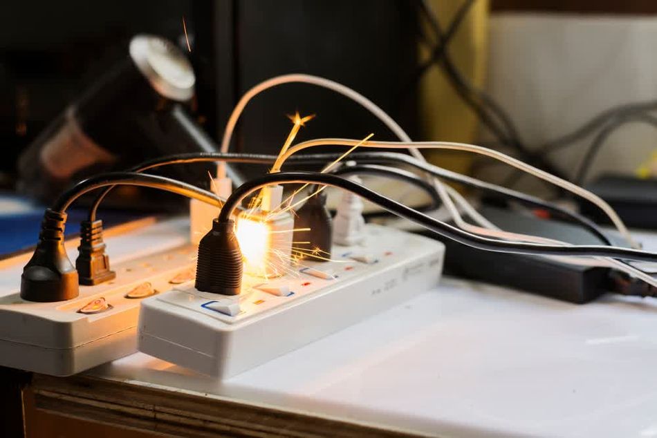
Overheating: The excessive current flow generates intense heat, which can melt insulation, damage components, and potentially start fires.
Fire Hazards: The extreme heat generated by a short circuit can ignite surrounding materials, leading to electrical fires.
Equipment Damage: The sudden surge of current can destroy sensitive electronic components and damage power sources.
Electrical Shock: Short circuits can create unexpected current paths, increasing the risk of electrical shock to individuals.
Power Outages: In larger systems, short circuits can trigger protective devices, causing widespread power interruptions.
The effect of short circuits on current flow and power dissipation is dramatic.
According to Ohm's Law (I = V/R), as resistance (R) approaches zero, current (I) tends towards infinity, limited only by the power source's capacity and any residual resistance in the circuit. This results in a massive increase in power dissipation (P = I²R), despite the low resistance, due to the extremely high current.
Hazards and Identification
Short circuits pose significant hazards in various electrical systems, from household appliances to industrial equipment. Common short circuit scenarios include:
Residential wiring: Damaged insulation in walls or appliances causing wire-to-wire contact.
Automotive systems: Battery terminals touching metal parts of the vehicle frame.
Electronic devices: Liquid spills create conductive paths on circuit boards.
Industrial machinery: Metal shavings bridging electrical contacts in control panels.
Power distribution: Tree branches fall on power lines, creating a path to the ground.
Detecting short circuits is crucial for preventing potential disasters. Techniques for identification include:
Visual inspection: Look for signs of burning, melted insulation, or discoloration.
Odor detection: Smell for burning odors, which often indicate a short circuit.
Thermal imaging: Use infrared cameras to detect abnormal heat patterns in electrical systems.
Continuity testing: Use multimeters to check for unexpected low-resistance paths.
Current measurement: Monitor for an abnormally high current draw in circuits.
Voltage drop analysis: Measure voltage at different points to identify unexpected drops.
Role of Circuit Breakers
Circuit breakers and fuses play a vital role in protecting against short circuits. There are two main types of devices:
Circuit breakers: These devices automatically interrupt the circuit when they detect excessive current flow. They can be reset after addressing the short circuit, making them reusable.
Fuses: These are sacrificial devices that melt when exposed to overcurrent conditions, breaking the circuit. They must be replaced after activation.
Both devices work on the principle of responding to the heat generated by excessive current flow.
Circuit breakers use either a bimetallic strip that bends when heated or an electromagnetic mechanism that trips when current exceeds a set threshold. Fuses contain a metal wire or strip that melts when the current exceeds its rated capacity.
Preventing and Mitigating Circuit Anomalies
Best Practices for Circuit Design
Effective circuit design is crucial for preventing both open circuits and short circuits, ensuring the reliability and safety of electrical systems. Implementing best practices during the design phase can significantly reduce the risk of circuit anomalies and their associated hazards.
Best practices for preventing open circuits and short circuits in circuit design include:
Robust connection design: Use secure terminal blocks, crimp connectors, or soldered joints to minimize the risk of loose connections that can lead to open circuits.
Strain relief: Incorporate strain relief mechanisms for cables and wires to prevent mechanical stress from causing open circuits.
Redundancy: Implement redundant paths for critical circuits to maintain functionality even if one path becomes open.
Proper component spacing: Ensure adequate spacing between conductive parts to reduce the risk of short circuits due to accidental contact.
Conformal coating: Apply conformal coatings to printed circuit boards (PCBs) to protect against moisture and contaminants that could cause short circuits.
Fuse and circuit breaker integration: Incorporate appropriate overcurrent protection devices to mitigate the effects of short circuits.
Thermal management: Design for proper heat dissipation to prevent thermal stress that can lead to component failure and potential short circuits.
EMI/EMC considerations: Implement proper EMI shielding and filtering to reduce electromagnetic interference that could cause circuit malfunctions.
Proper insulation, grounding, and circuit protection devices play a vital role in preventing circuit anomalies. Insulation prevents unintended current paths and protects against short circuits, while proper grounding ensures safety and helps in managing fault currents. Circuit protection devices like fuses, circuit breakers, and ground fault circuit interrupters (GFCIs) provide crucial safeguards against overcurrent and ground fault conditions.
Guidelines for selecting appropriate components to minimize circuit vulnerabilities:
Choose components with appropriate voltage and current ratings, including a safety margin.
Select components with suitable temperature ratings for the intended operating environment.
Use high-quality, reputable brands for critical components to ensure reliability.
Consider the mechanical strength of components, especially for applications subject to vibration or physical stress.
Evaluate the mean time between failures (MTBF) for components in long-life applications.
Select components with built-in protection features when available (e.g., reverse polarity protection, ESD protection).
Maintenance and Safety Protocols
Regular maintenance and adherence to safety protocols are crucial for preventing open and short circuits in existing electrical systems. Proper maintenance procedures help identify potential issues before they escalate into serious problems, while safety protocols ensure that workers do not inadvertently create circuit anomalies during maintenance or operation.
Safety protocols for working with electrical systems include:
De-energizing circuits before performing maintenance, using lock-out/tag-out procedures.
Using appropriate personal protective equipment (PPE) such as insulated gloves and safety glasses.
Employing insulated tools designed for electrical work to prevent accidental short circuits.
Maintaining a clean and organized work area to reduce the risk of accidental contact with live parts.
Following proper grounding procedures when working on electrical equipment.
Using voltage testers to verify that circuits are de-energized before beginning work.
Avoid wearing metallic jewelry or accessories that could cause short circuits.
Suggested Reading: What Is In-Circuit Testing? An Essential Guide for Engineers
Table comparing preventive measures for open circuits and short circuits:
Preventive Measure | Open Circuits | Short Circuits |
Connection Inspection | Check for loose or corroded connections | Ensure proper insulation and spacing between conductors |
Strain Relief | Implement cable management to prevent wire fatigue | Secure cables to prevent movement and potential contact |
Environmental Protection | Seal enclosures to prevent moisture ingress | Apply conformal coating to PCBs to prevent conductive contamination |
Thermal Management | Monitor for overheating that can lead to wire breaks | Ensure proper cooling to prevent insulation breakdown |
Vibration Control | Use shock-absorbing mounts for components | Secure all parts to prevent unintended contact during vibration |
Protective Devices | Implement redundant paths for critical circuits | Install fuses or circuit breakers for overcurrent protection |
Regular Testing | Perform continuity tests to check for open circuits | Conduct insulation resistance tests to detect potential short circuits |
Educating in Laymen’s Terms
Here are some quick tips for educating non-technical personnel about circuit safety:
Develop simple, visual guides that illustrate basic electrical safety concepts.
Conduct regular safety briefings that focus on recognizing and reporting potential electrical hazards.
Use relatable analogies to explain the dangers of open and short circuits (e.g., water flow in pipes).
Provide hands-on demonstrations of proper and improper electrical practices using safe, low-voltage setups.
Create a clear reporting system for employees to notify maintenance personnel of any observed electrical issues.
Emphasize the importance of not attempting repairs or modifications without proper training and authorization.
Teach the basics of reading warning labels and electrical ratings on equipment and appliances.
Incorporate electrical safety into general workplace safety training programs.
Conclusion
Open and short circuits are fundamental electrical concepts with significant implications. Open circuits obstruct current flow due to infinite resistance, while short circuits allow excessive current, potentially damaging components. Understanding these phenomena is crucial for designing, troubleshooting, and maintaining electrical systems.
Proficiency in managing open and short circuits is essential for electrical engineers. This knowledge drives decisions about component selection, circuit protection, and safety protocols. As technology evolves, advanced tools like AI and smart diagnostics will aid in circuit anomaly detection, but a strong foundation in basic circuit behavior remains indispensable.
Frequently Asked Questions
What is the main difference between an open circuit and a short circuit?
An open circuit has infinite resistance, preventing current flow, while a short circuit has near-zero resistance, allowing excessive current flow.
How can I detect an open circuit in my electrical system?
Open circuits can be detected through visual inspection, continuity testing with a multimeter, or by observing symptoms like non-functioning components in the affected circuit.
What are the most common causes of short circuits?
Common causes include damaged insulation, loose connections, water ingress, and conductive debris bridging circuit elements.
Can a short circuit cause a fire?
Yes, short circuits can cause fires due to the excessive heat generated by the high current flow, which can ignite surrounding materials.
How do circuit breakers protect against short circuits?
Circuit breakers detect the abnormally high current caused by a short circuit and quickly interrupt the circuit to prevent damage and potential fires.
What's the difference between a fuse and a circuit breaker in protecting against short circuits?
Fuses are single-use devices that melt when exposed to overcurrent, while circuit breakers can be reset and reused after tripping due to a short circuit.
How can I prevent open and short circuits in my electronic designs?
Prevent open circuits by ensuring secure connections and proper strain relief, and prevent short circuits by maintaining adequate spacing between conductors, using appropriate insulation, and implementing overcurrent protection devices.
References
Open Circuit: What is it? (And How Does it Differ To a Short Circuit) (electricalvolt.com)
Voltage, Current, Resistance, and Ohm's Law - SparkFun Learn
Open Circuit and Short Circuit Test on Transformer - ElectronicsHub USA
Short Circuits and Open Circuits: Causes, Consequences, and Prevention - Ocsaly
Table of Contents
IntroductionOpen Circuit vs Short Circuit: A Comprehensive ComparisonDefining the ExtremesElectrical Behavior AnalysisImpact on Circuit ComponentsContextual Study of Open and Short Circuits Current Flow and ResistanceVoltage and Power in CircuitsOpen Circuits: The Path of Infinite ResistanceCharacteristics and CausesConsequences and DetectionShort Circuits: When Resistance Approaches ZeroAnatomy and ImplicationsHazards and IdentificationRole of Circuit BreakersPreventing and Mitigating Circuit AnomaliesBest Practices for Circuit DesignMaintenance and Safety ProtocolsEducating in Laymen’s TermsConclusionFrequently Asked QuestionsReferences