Optical Encoder Technology: Advanced Guide to Precision Motion Control Systems
This article explores the principles behind optical encoders, their types, and their advantages, highlighting how they enhance performance, ensure accuracy, and meet demanding standards in complex control environments.
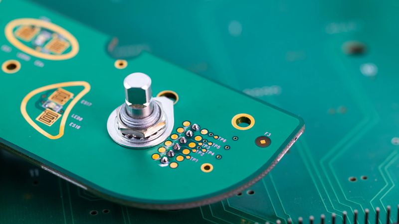
Optical Encoder; Credits: grayhill.com
Introduction
Optical encoders are crucial in modern precision motion control systems, providing high-resolution position and velocity feedback with accuracies reaching sub-micron levels. These optoelectronic devices translate mechanical motion into digital signals through a precise combination of photoelectric detection and optical gratings. Optical encoders operate on the principles of light interruption and detection, achieving resolution capabilities exceeding 1 million counts per revolution.
Their superior noise immunity, coupled with fast response times typically under 1 microsecond, enables real-time position tracking in demanding industrial environments. The direct digital output eliminates the need for analog-to-digital conversion, reducing signal processing overhead and improving system reliability. In modern manufacturing, semiconductor processing, and precision instrumentation, optical encoders serve as the primary feedback mechanism for closed-loop control systems. This enables precise motion control, essential for advanced automation and robotics.
Fundamentals of Optical Encoders
Optical encoders are devices that convert mechanical motion into electrical signals, providing critical position feedback in control systems. Curious about how encoders work?
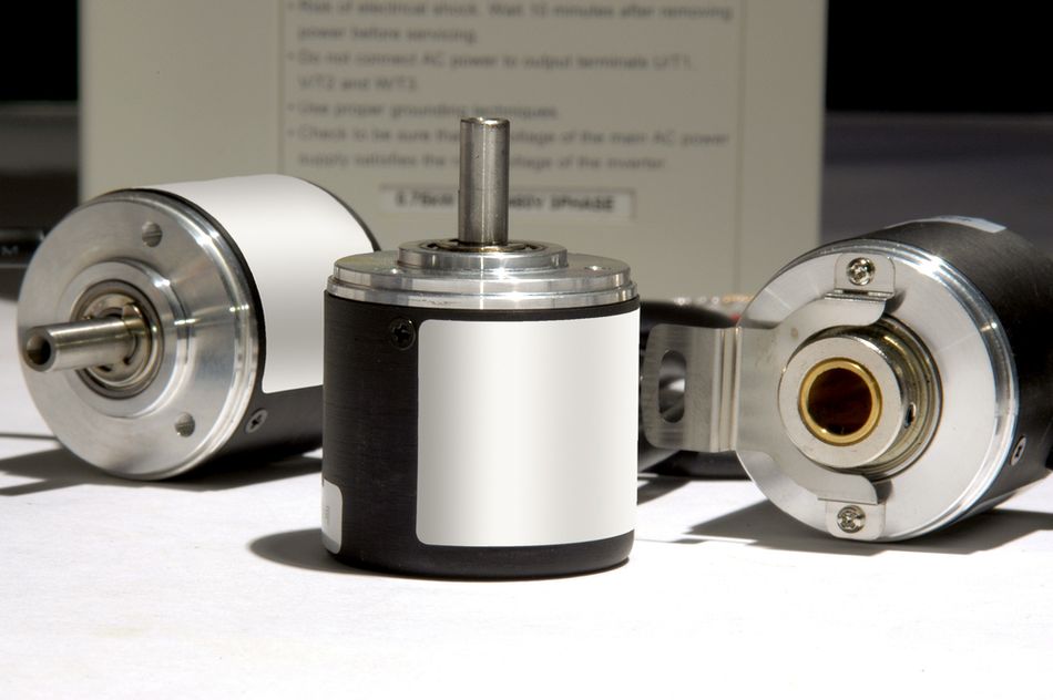
These devices function by detecting the movement of an encoder disk or code wheel, which has a specific pattern that allows position feedback. The disk typically contains alternating transparent and opaque sections, which modulate a light source, such as an LED light. When the light passes through the disk, it interacts with a photosensor or photodetector (often a photodiode) that generates a digital signal. This process converts the analog mechanical position of an encoder into a digital signal that a control system can use.
Types of Optical Encoders
Optical encoders come in two main types: rotary and linear. Each serves distinct purposes and is selected based on the application’s movement requirements — whether rotational or linear.
Rotary Encoders: Used to track angular position and direction, with applications in high-performance systems needing absolute position or relative position data.
Linear Encoders: Detect linear movement, typically in robotics and automation environments, where accurate position information is required for precision tasks.
Key Terms and Concepts
Understanding specific terminology is crucial when working with optical encoders, as each parameter affects the resolution, accuracy, and suitability of an encoder for different applications.
PPR (Pulses Per Revolution): A measure of the resolution of an encoder, indicating how many pulses are generated per full rotation of the encoder disk.
Incremental Optical Encoders: These measure relative position by counting pulses from a starting point, commonly used in general motion control.
Absolute Optical Encoders: Provide a unique signal for each position on the disk, allowing for absolute position tracking, essential in mission-critical applications.
Advantages of Optical Encoders
Optical encoders are preferred in automation and control systems for several reasons:
High Resolution and Accuracy: Optical encoders offer exceptionally high resolutions, often exceeding 25 PPR, which is ideal for precise position feedback.
Robust Performance in Harsh Environments: Many optical encoders are built with IP67-rated enclosures, providing dust and water resistance.
Fast Response Time: With fast digital signal generation, optical encoders can provide real-time position data, critical in high-speed applications like robotics and CNC machining.
Versatile Output Options: Optical encoders generate square waves, pulse signals, or digital signals compatible with various control systems.
In sum, optical encoders are essential components in modern motion control and automation systems. These feedback devices convert mechanical motion into accurate, real-time position information for control systems across various industries.
Signal Generation and Detection Architecture
Optical-Electronic Interface Design
The optical-electronic interface in encoders operates on the photoelectric effect principle, where photons striking a semiconductor material generate electron-hole pairs. This quantum-level interaction occurs within specially designed photodiodes, typically silicon-based, with quantum efficiencies reaching 85% at optimal wavelengths. [1]
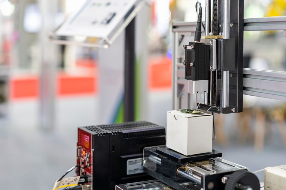
Light generation relies on precision-engineered LED or laser sources operating in the near-infrared spectrum (850-940nm). These sources must maintain stable output intensity across operating temperatures from -40°C to +85°C, with typical power outputs ranging from 0.5mW to 2mW.
The light source emits a beam of light that is modulated by the code disc of an encoder. The code disc, a precisely patterned disk with alternating opaque and transparent segments, interrupts the light beam as it rotates or translates. This modulation creates a unique pattern of light and dark pulses that corresponds to the position of an encoder.
Photodetector converts the modulated light signal into an electrical signal. These arrays utilize differential configurations to maximize noise immunity. The most common arrangement employs quadrature detection with four photosensitive elements spaced 90° electrically apart. The common types of photodetectors used in optical encoders include:
Photodiodes: These devices directly convert light into electrical current. They are widely used in optical encoders due to their high sensitivity, fast response time, and wide dynamic range.
Phototransistors: These devices amplify the photocurrent generated by incident light, resulting in a larger output signal. They are often used in applications where high sensitivity is required.
Signal conditioning requires precision trans-impedance amplifiers with bandwidth exceeding 1MHz and input bias currents below 1nA. [2] The circuit implements automatic gain control (AGC) to maintain signal integrity across varying light intensities. Here's the comprehensive overview:
| Light Source Type | Wavelength (nm) | Power Output (mW) | Beam Divergence | Lifetime (hrs) |
| IR LED | 850 | 0.5-1.0 | 20° | 50,000 |
| VCSEL | 850 | 1.0-2.0 | 12° | 100,000 |
| Red LED | 660 | 0.3-0.8 | 25° | 40,000 |
Optical encoders rely on precise light modulation and detection to deliver accurate position data. This advanced optical-electronic interface ensures high performance in demanding motion control applications.
Code Disc Engineering
Code disc engineering in optical encoders is a precise process involving mathematical and material considerations that ensure accurate position measurement and signal reliability. The design relies on specific formulas that guide the spatial distribution and density of patterns on the disc, essential for generating clear signals.
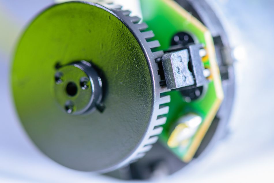
The mathematical foundation of code disc design centres on the relationship between the disc radius and pattern spacing. This is governed by the equation:
where r represents the disc radius and n denotes the number of line patterns. This relationship determines the spatial frequency of encoded information across the circumference of the disc.
Resolution directly correlates with the number of line patterns, expressed as n, where n represents the count of distinct coded elements. Higher resolution demands more densely packed patterns, requiring precise manufacturing tolerances and superior optical discrimination.
Three primary coding methodologies dominate encoder disc design:
| Coding Type | Key Characteristics | Application Scenario |
| Incremental | Simple Pattern, Relative Position Tracking | General Motion Control |
| Absolute | Complex Pattern, Absolute Position Reading | Mission Critical Systems |
| Differential | Dual Track Design, Enhanced Noise Immunity | High Interference Environments |
The minimum line width calculation follows the equation:
where manufacturing limitations typically constrain this to no less than 10 micrometres. This physical constraint often determines the practical resolution limit of the encoder system.
Material selection for the code disc is another critical factor, impacting durability, stability, and accuracy. Key materials include:
| Material | Primary Advantage | Key Limitation |
| Glass | ±0.5μm Precision | Fragile |
| Metal | Temperature Stable | Higher Cost |
| Plastic | Cost Effective | Lower Accuracy |
Glass offers unmatched precision, but is fragile and may not withstand harsh environments. Metal provides stability across temperature variations, though it is more expensive, while plastic is economical but sacrifices accuracy.
Together, these design factors — from mathematical pattern distribution to material selection — ensure that the code disc is capable of precise motion tracking. This makes it a critical component in high-performance optical encoders.
Recommended Reading: What is an Encoder: Understanding the Basics and Beyond
Signal Processing and Interpretation
In optical encoders, signal processing and interpretation play a pivotal role in achieving precise position feedback. This involves analyzing and enhancing quadrature signals to maximize resolution and ensure accuracy in position detection. Here’s an in-depth look at the mechanisms involved.
Quadrature Signal Analysis and Enhancement
Quadrature encoding relies on two phase-shifted signals, 𝐴 and 𝐵, each offset by 90 electrical degrees. [3] These signals, when interpreted together, allow for precise directional and positional tracking, essential for high-resolution applications. The positional calculation is expressed as:
where 𝑛 is the revolution count, providing an absolute measure of the position across the rotations of an encoder.
Phase relations for the quadrature signals are:
This 90° phase shift allows the determination of both the direction and precise timing of movement.
Error detection employs Lissajous analysis, where the ideal relationship between signals 𝐴 and 𝐵 forms a circular Lissajous pattern:
Deviations from this ideal circle indicate signal degradation, such as noise or interference, which can then be corrected to maintain signal integrity.
Interpolation techniques enhance basic resolution. Basic resolution is enhanced by dividing each signal cycle into smaller increments, enabling finer position measurement. Some common methods include:
Simple Division: A low-processing method providing a 4x resolution gain.
Sine Fitting: Achieves a 10x-50x gain by fitting sine waves, suitable for medium accuracy needs.
Phase-Locked Loop (PLL): Enables 100x-1000x resolution gain with high accuracy, though it requires more processing power.
Advanced interpolation often leverages arctangent calculations for precise phase positioning:
Practical Limitations include a maximum interpolation factor of 1024x the base resolution and a noise floor at approximately -60dB, requiring careful bandwidth management.
Signal processing faces bandwidth limitations, expressed as:
Temperature drift and phase matching further affect signal accuracy, with phase matching typically maintained within ±2.5° electrical.
In conclusion, quadrature encoding, with advanced interpolation and careful signal conditioning, provides precise positional and directional tracking. This ensures high accuracy in motion control applications even under challenging conditions.
Error Sources and Compensation
Optical encoder accuracy faces six primary error sources, each requiring specific compensation strategies. Mechanical misalignment introduces angular offsets resulting in sinusoidal position errors following the equation:
where 𝐴 and 𝐵 represent misalignment magnitudes in orthogonal axes.
Electromagnetic interference generates noise following a Gaussian distribution:
Compensation algorithms employ multiple strategies:
Gain Calibration adjusts the amplitude of the output signal to counteract variations due to temperature fluctuations, component ageing, or minor manufacturing inconsistencies. The adjusted gain is calculated using the formula:
Offset Correction eliminates unwanted baseline shifts or offsets in the output signal, which can occur due to temperature drift, mechanical alignment issues, or electronic noise. Offset compensation uses the formula:
Digital Filtering smooths out noise and enhances the accuracy of the position data by isolating the desired signal from high-frequency disturbances. Filters are designed to target specific noise frequencies, applying a mathematical operation:
The total error in the system is estimated through a root-sum-square approach:
The calibration procedure implements a six-step process:
Mechanical alignment verification
Initial error measurement
Gain calibration application
Offset compensation
Performance verification
Filter optimization
Each source of error has its typical magnitude and corresponding compensation technique:
| Error Source | Typical Magnitude (μm) | Compensation Method |
| Mechanical Misalignment | 5.0 | Precision Mounting |
| Noise Interference | 2.0 | Digital Filtering |
| Temperature Variation | 1.0 | Thermal Compensation |
| Component Aging | 3.0 | Regular Calibration |
| Resolution Limitation | 0.5 | Interpolation |
By addressing each of these factors, optical encoders achieve high-resolution, accurate signal processing critical for precision motion control applications.
Recommended Reading: Absolute Encoder: Precision Positioning in the Digital Age
Implementation and System Integration
Communication Interfaces and Protocols
Modern optical encoders use several communication protocols that facilitate high-speed data transfer and precise position tracking. BiSS-C and EnDat 2.2 are the leading protocols in industrial applications, offering low-latency communication and robust error detection. [4]
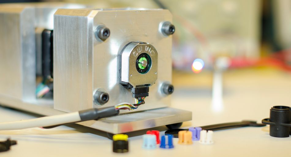
The BiSS-C protocol operates at clock frequencies up to 10 MHz, supporting real-time position updates with cycle times as low as 12.5 μs. Error detection is handled by a CRC-6 code, ensuring data integrity over long cables up to 100 meters. EnDat 2.2 achieves similar performance with 8 MHz clock rates and 10 μs cycle times. This protocol uses a CRC-5 code for error detection, with support for 100-meter cables.
Bandwidth requirements follow the equation:

Maintaining real-time performance requires careful management of several factors:
Propagation Delay: Should remain under 100 ns to minimize latency.
Processing Latency: Ideally kept below 1 μs for timely data processing.
Jitter Tolerance: Managed within a ±5 ns limit to ensure signal stability.
Clock Stability: Maintained within ±50 ppm, essential for accurate timing over extended periods.
These factors are crucial in applications where even small delays or inconsistencies can impact system accuracy and efficiency.
Each protocol offers unique features suited to different applications. Let’s see their comparison:
| Interface | Max Speed | Latency | Cable Length | Error Detection |
| BiSS-C | 10 MHz | 12.5 μs | 100m | CRC-6 |
| EnDat 2.2 | 8 MHz | 10 μs | 100m | CRC-5 |
| SSI | 2 MHz | 25 μs | 50m | None |
| Hiperface | 9.6 MHz | 500 μs | 50m | Parity |
Choosing the most suitable protocol involves calculating a score that balances bandwidth, real-time capability, latency, and power efficiency:
where,
BW: Available bandwidth
RT: Real-time capability
L: Latency
P: Power consumption
A higher score indicates a protocol better suited for high-speed, low-latency applications. This makes it a valuable metric in selecting the optimal communication protocol for a specific industrial setup.
The choice of communication protocol in optical encoders depends on a careful balance of speed, real-time requirements, error detection, and system demands. Through proper selection, these protocols enable high-speed, reliable communication critical for today’s precision-driven industries.
System Integration Guidelines
Integrating optical encoders into motion control systems demands strict compliance with alignment, tolerance, and environmental specifications to ensure peak performance. These guidelines aim to prevent misalignment, reduce errors, and maintain consistent signal quality throughout operation.
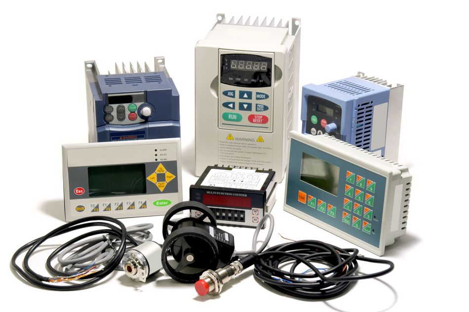
Precise alignment is essential for achieving accurate position feedback. Key parameters include:
Mounting Tolerance: Achieving a mounting accuracy of ±0.05 mm is crucial for consistent signal generation. This level of precision minimizes positional errors and ensures optimal encoder function.
Angular Misalignment: Angular deviations must be limited to ±0.5 degrees. Even slight angular misalignment can result in cumulative errors, affecting the encoder’s ability to provide accurate position data.
Parallelism: The encoder mounting surface should have a deviation of no more than 0.1 mm to prevent misalignment over time. This ensures that the encoder remains level and stable, reducing wear and tear.
Offset Distance: Maintaining a minimum offset distance of 10 mm from adjacent components is recommended to minimize electromagnetic interference and prevent signal distortion.
Tolerance analysis helps to understand the cumulative effect of minor deviations in alignment, component variation, and environmental factors. Each parameter’s impact is categorized by its level of influence on encoder performance. Comprehensive tolerance analysis reveals cumulative system variations:
| Parameter | Tolerance | Impact |
| Mechanical Alignment | ±0.05 mm | Primary |
| Signal Processing | ±5 ns | Secondary |
| Component Variation | ±0.1% | Tertiary |
| Temperature | ±1°C | Environmental |
Optical encoders are often used in challenging environments, so ensuring their durability and stability is critical. Here are a few environmental considerations:
Operating Temperature: Encoders should function reliably in temperatures ranging from -40°C to +85°C to handle various climate conditions.
Humidity Tolerance: Encoders need to withstand humidity levels up to 95% non-condensing to prevent corrosion and ensure longevity.
Vibration Resistance: Encoders are designed to tolerate vibrations of up to 10g at 55Hz, making them suitable for use in high-motion applications where vibrations are common.
EMI/RFI Shielding: Electromagnetic and radio frequency interference can distort encoder signals. Proper shielding is essential to maintain data integrity in environments with high interference.
Protection Rating: Encoders with an IP67 rating are protected against dust and water, making them suitable for harsh and outdoor environments.
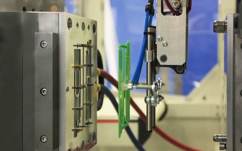
For reliable integration, rigorous system testing and verification ensure that encoders meet all design specifications:
Laser Alignment Tool: Use a laser alignment tool to confirm initial setup accuracy, minimizing initial misalignment risks.
Diagnostic Output Validation: Check the output of the encoder for consistency and accuracy, ensuring that all signals meet operational standards.
Load Condition Testing: Assess the encoder’s performance under various operational loads to verify durability and accuracy during standard use.
Oscilloscope Signal Analysis: Use an oscilloscope to analyze signal waveform integrity, identifying potential noise or signal distortion.
Temperature Variation Assessment: Validate performance across the encoder’s specified temperature range to ensure stable output.
Following a detailed checklist ensures a smooth installation process and reliable initial operation:
Model Verification: Confirm that the encoder model meets all system specifications.
Mechanical Alignment: Ensure accurate alignment with the specified tolerances to minimize operational errors.
Electrical Connection Validation: Double-check all connections for security and correct configuration.
Safety Barrier Installation: Install any required safety barriers to protect the encoder and surrounding components.
Control System Compatibility: Verify that the encoder output aligns with the control system's input requirements.
Initial Operation Testing: Run initial tests to detect any installation issues, resolving them promptly to ensure smooth operation.
By following these guidelines, protocols, and systematic checks, optical encoders can be successfully integrated into precision motion control systems. This helps ensure that encoders operate reliably, providing accurate data essential for high-performance industrial and automation environments.
Recommended Reading: Motion Control in Robotics: 4 Types of Motors for Industrial Robots
Conclusion
Optical encoder implementation success comprises three critical technical factors: signal integrity maintenance, precise mechanical alignment, and optimal signal processing. Performance optimization requires careful attention to environmental factors, particularly temperature stability within ±1°C and vibration isolation above 55Hz. Implementation of best practices demands rigorous adherence to mounting specifications, regular calibration intervals not exceeding 1000 operating hours, and comprehensive error budgeting accounting for both systematic and random errors. Signal conditioning circuits must maintain bandwidth capabilities exceeding 1MHz while ensuring noise immunity better than -60dB.
Frequently Asked Questions
Q: What is a transmissive optical rotary encoder?
A. A transmissive optical rotary encoder, also known as an optical shaft encoder, is an electromechanical device that is used to measure and control rotational motion. It's widely used in various industries, including automation, robotics, and machine control.
Q. How does an optical encoder differ from other types of encoders?
A. Optical encoder modules use light to detect motion, typically offering higher resolution and accuracy than magnetic or capacitive encoders. They are ideal for environments where precise position tracking is essential.
Q: What methods optimize resolution beyond manufacturer specifications?
A: Resolution enhancement requires the implementation of advanced interpolation techniques. Utilize sine-cosine interpolation with error mapping, achieving up to 4096x interpolation factor. Critical factors include signal-to-noise ratio >40dB and phase relationship maintenance within ±2.5°.
Q: How should multiple encoder systems be synchronized?
A: System synchronization requires master-slave configuration with deterministic timing. Implement hardware triggering with a maximum skew of 100ns between devices. Use distributed clock synchronization protocols maintaining better than 1μs precision across the system.
Q: What environmental factors should be considered when installing an optical encoder?
A: Optical encoders should operate within their specified temperature range (e.g., -40°C to +85°C), have humidity tolerance (up to 95% non-condensing), and be protected from vibrations, EMI, and RFI interference. IP67-rated encoders are recommended for harsh environments due to their dust and water resistance.
References
[1] MDPI. Silicon-Based Avalanche Photodiodes: Advancements and Applications in Medical Imaging [Cited 2024 November 05] Available at: Link
[2] TI. What You Need to Know about Transimpedance Amplifiers [Cited 2024 November 05] Available at: Link
[3] allaboutcircuits. Understanding I/Q Signals and Quadrature Modulation [Cited 2024 November 05] Available at: Link
[4] motioncontroltips. Absolute encoder interfaces: Differences between SSI, BiSS, Hiperface, and EnDat [Cited 2024 November 05] Available at: Link
Table of Contents
IntroductionFundamentals of Optical EncodersTypes of Optical EncodersKey Terms and ConceptsAdvantages of Optical EncodersSignal Generation and Detection ArchitectureOptical-Electronic Interface DesignCode Disc EngineeringSignal Processing and InterpretationQuadrature Signal Analysis and EnhancementError Sources and CompensationImplementation and System IntegrationCommunication Interfaces and ProtocolsSystem Integration GuidelinesConclusionFrequently Asked QuestionsReferences


