PCB Components: A Comprehensive Technical Guide to Passive, Active, and Electromechanical Parts
This article provides an in-depth overview of the various PCB components that make up electronic circuits – from passive elements like resistors and capacitors to active semiconductors and electromechanical devices.

21 Mar, 2025. 19 minutes read
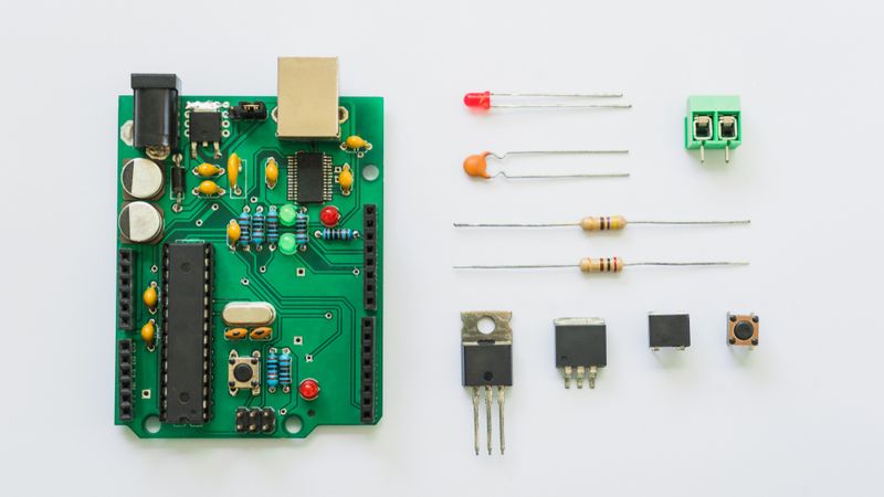
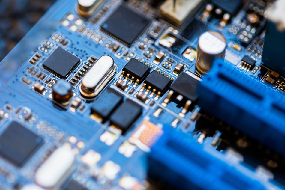
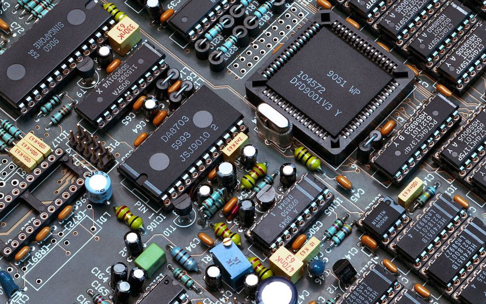
PCB Board with electronic components: Resistor, ICs, Capacitor, Switch, and Connector
Introduction
Printed circuit boards (PCBs) are the foundation of modern electronic devices, and PCB components are the building blocks mounted on these boards. In every electronic gadget – from smartphones and computers to automobiles and industrial machines – you will find a PCB populated with various electronic components. These components are broadly classified into three categories:
1. Passive PCB components, such as resistors and capacitors, regulate electrical signals without amplification or switching functions.
2. Active PCB components, including transistors and integrated circuits (ICs), control signal flow and enable complex electronic operations.
3. Electromechanical PCB components, like connectors and relays, facilitate physical interactions between electrical circuits and external devices.
Understanding the role and functionality of each category is crucial for engineers and designers aiming to optimize PCB performance!
Passive PCB Components
Passive PCB components are electrical parts that do not generate or amplify energy; instead, they absorb, store, or release energy in a circuit. Unlike active devices, passive components do not require any external power to perform their function – they rely only on the electrical signals present in the circuit.
Let’s discuss the key passive components and their roles:
Resistors
A resistor is a passive two-terminal component that resists the flow of electric current, introducing a precise amount of resistance into the circuit. Resistors are the basic building blocks of rectifiers, relays, fuses, and microcontrollers. By selecting appropriate resistor values, engineers can control current levels, divide voltages, and bias active devices in a circuit.

which relates the voltage drop, V, across the resistor to the current, I, flowing through it and its resistance value, R.
Resistors are one of the most common PCB components and serve many purposes. They are used as:
Pull Up or Pull Down Resistors to define logic levels on input pins in digital circuits
Voltage Divider Circuits to generate reference voltages for sensors and amplifiers
Current Limiting Applications, such as protecting LEDs from excessive current
Termination Resistors in high-speed signal lines to prevent reflections
Load Resistors to dissipate excess power and stabilize circuits
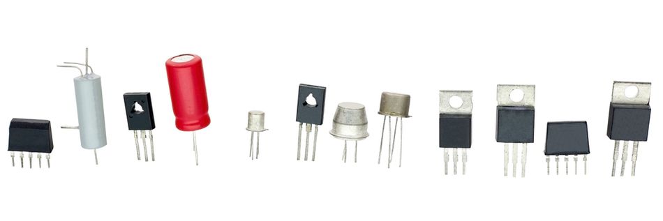
Resistors come in various types, each suited for specific applications:
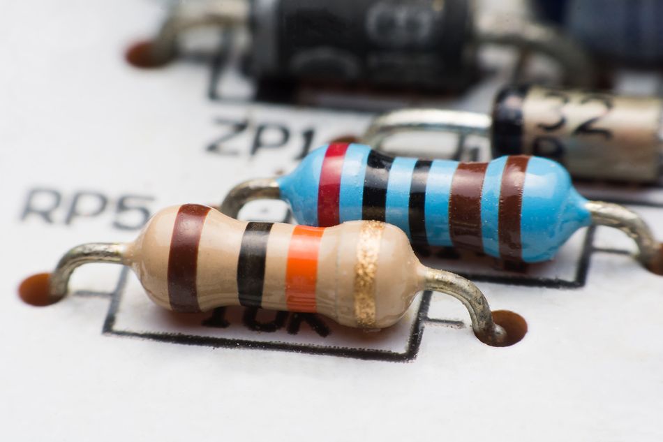
Carbon Film & Metal Film Resistors – Common for general-purpose use, available in cylindrical (through-hole) or rectangular (surface-mount) packages
Wire Wound Resistors – Used for high-power applications due to their ability to handle large currents
Thick Film & Thin Film Resistors – Precision resistors used in surface-mount technology (SMT)
When selecting a resistor, engineers consider:
Resistance value (Ω) – Defines current control capabilities
Tolerance (%) – Indicates accuracy (e.g., ±5% for general use, ±1% for precision circuits)
Power Rating (W) – Determines how much power it can safely dissipate without overheating (e.g., 0.25W, 1W)
Resistors are available in THT (Through Hole Technology) packages (color-coded bands for resistance value) and SMD (Surface Mount Device) packages (numeric markings). The choice depends on assembly methods—through-hole parts allow manual soldering, while SMDs enable automated production and higher component density.
Recommended Reading: SMD Resistor Sizes: A Comprehensive Guide for Engineers
Capacitors
A capacitor is a passive component that stores energy in an electric field by accumulating an electrical charge difference between its two plates. In practical terms, a capacitor temporarily holds an electric charge and can release it when needed, acting like a small rechargeable battery for AC signals.
where Q is the charge stored, V is the voltage, and C is the capacitance
Typical useful capacitors range from very small values (picofarads, pF) used in high-frequency circuits, to (microfarads, µF) or even millifarads for power supply filtering. The common capacitor values on PCBs range from ~1 pF up to thousands of µF for large electrolytic capacitors.
Capacitors serve multiple roles in PCB circuits:
Coupling Capacitors – Pass AC signals while blocking DC bias, commonly used in audio and RF circuits
Decoupling (Bypass) Capacitors – Smooth voltage fluctuations and suppress noise in power supplies
Filtering Applications – Used in RC and LC filters to select or block specific frequencies
Timing Circuits – Combined with resistors to set time delays or oscillator frequencies
Tuning Circuits – Combined with radio frequency oscillators to set frequencies
Energy Storage – Stabilize power supply rails by storing and releasing energy when needed
Each type of capacitor has unique advantages:
Ceramic Capacitors – Non-polarized, ideal for high-frequency decoupling and general filtering applications
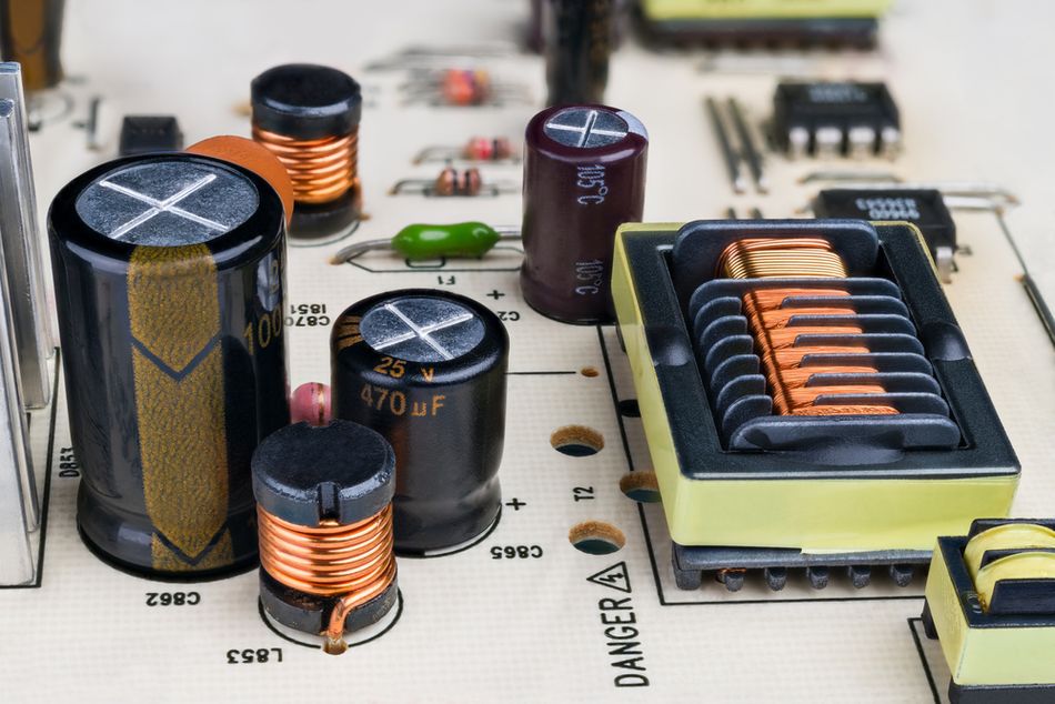
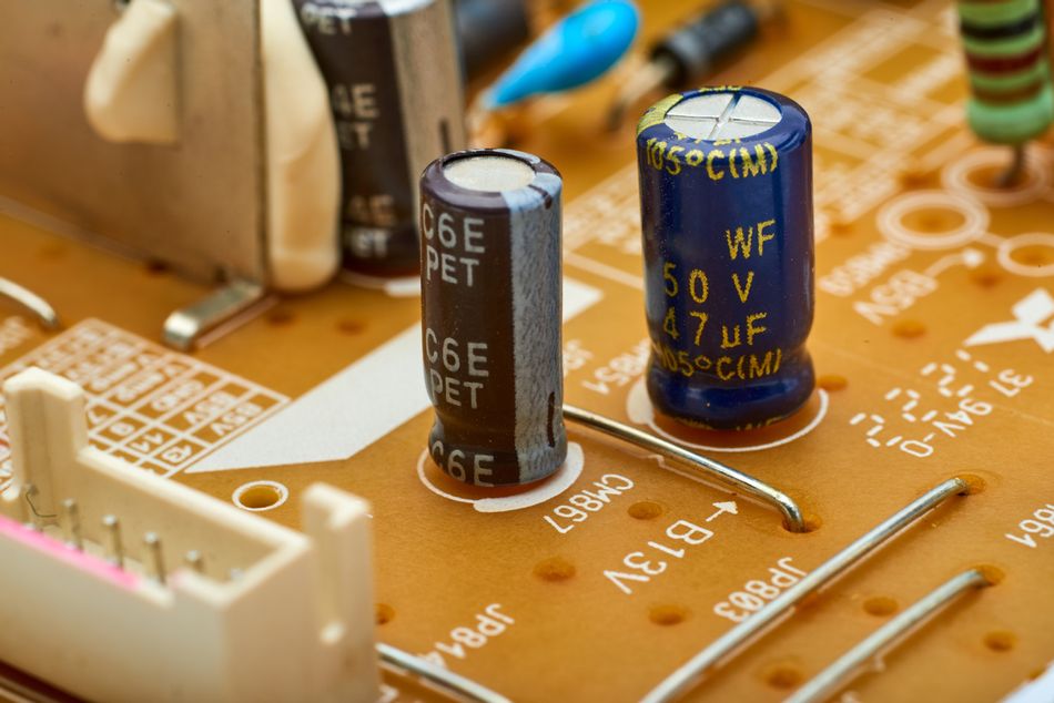
Electrolytic Capacitors – Polarized, high-capacitance components used for power supply smoothing
Film Capacitors – Dielectric: plastic film, excellent stability, used in audio and precision circuits
Tantalum Capacitors – Compact, high-performance alternatives to electrolytes, often used in space-constrained designs
The key selection parameters include:
Capacitance (F) – Determines charge storage capacity
Voltage Rating (V) – Maximum voltage a capacitor can handle (e.g., 16V, 50V)
Tolerance (%) – Indicates accuracy in capacitance value (e.g., ±5%, ±10%)
Package Type – Through-hole (easier for manual board assembly) or SMD (ideal for high-density PCB designs)
Often, designers use capacitors in parallel to optimize performance—for instance, pairing a 100µF electrolytic capacitor (bulk energy storage) with a 0.1µF ceramic capacitor (high-frequency noise filtering) in power supply circuits.
Recommended Reading: Capacitor Polarity: Ensuring Proper Orientation for Optimal Performance
Inductors
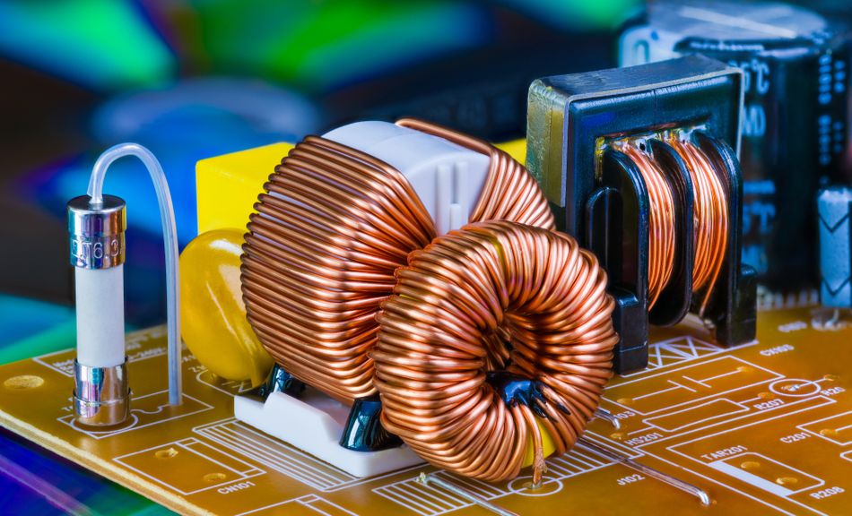
An inductor (also known as a coil or choke) is a passive component that stores electrical energy in a magnetic field when current flows through it. Physically, an inductor is typically a coil of wire (sometimes wrapped around a ferromagnetic core) that resists changes in current.
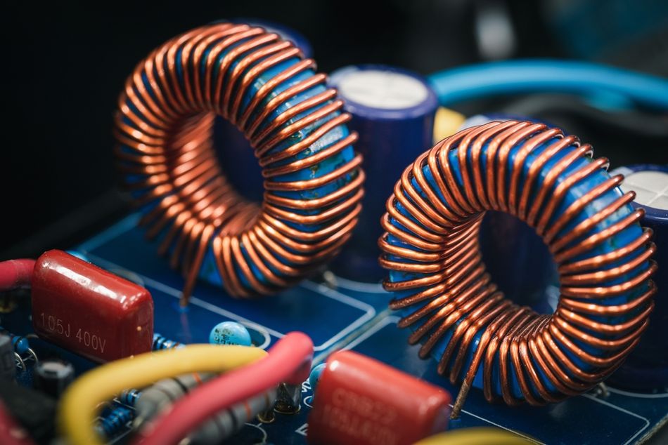
where L is inductance, µ is permeability, N is the number of turns in coil, A is the area encircled by coil, and l is the length of coil
Inductors tend to oppose changes in current: if current through an inductor attempts to increase, the inductor generates a voltage that opposes this change. This behavior makes inductors the complement of capacitors: inductors pass low-frequency (including DC) currents easily but impede high-frequency changes (they block AC and allow DC, in an ideal sense, opposite to the behavior of blocking DC and passing AC in capacitor).
Inductors are essential in power and signal processing applications:
DC-DC Converters – Store and transfer energy in switching regulators
EMI Suppression – Used as chokes to filter high-frequency noise from power lines
RF and Audio Filters – Create LC circuits for frequency selection in tuners and equalizers
Transformers – Utilize coupled inductors for voltage step-up, step-down, or isolation
Inductors vary in form and function:
Wire Wound Inductors – Provide high current handling for power applications
Ferrite Core Inductors – Used in RF and EMI filtering
Air Core Inductors – Offer stable performance at high frequencies
The key considerations include:
Inductance Value (H) – Determines opposition to AC changes
Current Rating (A) – Defines maximum allowable current before saturation
DC Resistance (DCR, Ω) – Affects efficiency due to power loss
Size & Frequency Response – High-frequency inductors require low parasitic capacitance
Recommended Reading: Extending the Battery Life of Hearables and Wearables with Single-Inductor Multiple-Output Switching Architecture
Other Passive Components
Passive components may be simple in function, but they are crucial for the stability and proper operation of circuits. They shape signal behavior and prepare conditions for active components to do their jobs.
Transformers: For circuits dealing with AC or where isolation is needed (like AC adapters, audio coupling transformers, or signal isolation modules), large power transformers are usually off-board due to size.
Ferrite Beads: These are small inductive components used primarily for filtering high-frequency noise (often placed on supply lines to block RF interference).
Potentiometers and Trimmers: These are adjustable resistors (typically a small knob or screw that changes a resistance value) used to fine-tune circuit parameters (for example, adjusting the contrast on a display or calibration settings). They are passive devices but involve a mechanical adjustment, often considered electromechanical passives.
Fuses: A fuse is a passive protective component – essentially a wire or material that melts and breaks the circuit if the current is above a certain threshold. [2] Fuses (or resettable polyfuses) are common on PCBs for over-current protection, especially at power inputs.
Next, we’ll examine active components, which bring electronics to life by amplifying and controlling those signals that passive parts help condition.
Active PCB Components
Active PCB components are essential for controlling voltages and currents in electronic circuits. Unlike passive components, active components require an external power source to function and can amplify, switch, or process electrical signals. These components typically contain semiconductor materials such as silicon or germanium and form the foundation of digital logic, amplification, power regulation, and signal processing in modern PCBs.
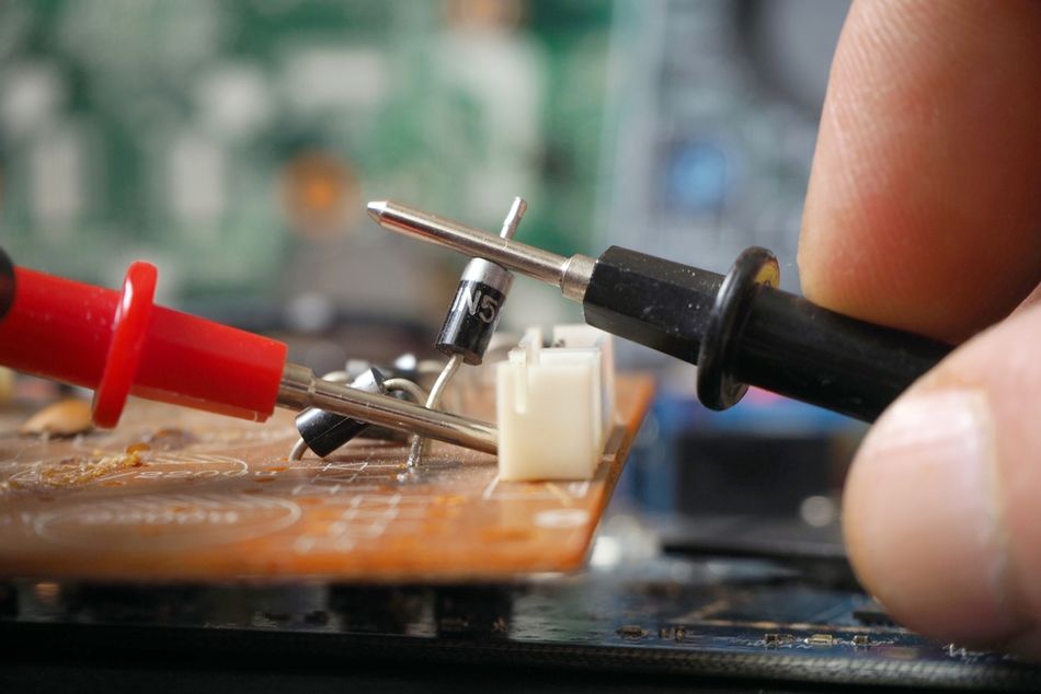
Diodes (and LEDs)
A diode is a two-terminal semiconductor device that allows current to flow primarily in one direction. It behaves like a one-way valve for electric current: when forward-biased (positive voltage on its anode relative to its cathode), a diode conducts current (after an initial forward voltage drop, about 0.7 V for silicon diodes). When reverse-biased, it blocks current (up to its breakdown voltage). This simple property makes diodes extremely useful for controlling the direction of current flow. [3]
Rectifier Diodes – Convert AC to DC in power supplies (e.g., 1N4007 for general rectification)
Switching Diodes – High-speed diodes used in digital logic and signal routing
Zener Diodes – Regulate voltage by maintaining a stable reference voltage when reverse-biased beyond their breakdown voltage (e.g., 5.1V Zener for voltage regulation)
Schottky Diodes – Low forward voltage drop (~0.2–0.3V) and fast switching, ideal for high-frequency circuits and power efficiency (e.g., 1N5819 in switching regulators)
Light-Emitting Diodes (LEDs) – Emit light when forward-biased, used for indicators, displays, and lighting applications. LEDs require a current-limiting resistor to prevent excessive current flow.
Let’s talk about the key characteristics:
Forward Voltage Drop – The voltage required to conduct (e.g., ~0.7V for silicon diodes, ~0.3V for Schottky diodes)
Reverse Breakdown Voltage – Determines the maximum reverse voltage a diode can withstand
Reverse Recovery Time – Important for high-speed switching applications
LED Brightness and Color – Defined by luminous intensity and wavelength
Diodes are available in through-hole packages (e.g., axial-leaded glass or plastic) and surface-mount packages (SOD-123, SOT-23, etc.), making them suitable for various PCB assembly methods.
Recommended Reading: How Does a Diode Work: Unraveling the Heart of Electronic Control
Transistors
Transistors are three-terminal semiconductor devices that function as amplifiers or switches in electronic circuits. They are essential in power regulation, digital logic, and signal amplification.
1. Bipolar Junction Transistors (BJTs) – Current-controlled devices with NPN and PNP configurations. They consist of collector, base, and emitter terminals. A small base current controls a larger collector-emitter current.
Use Cases: Signal amplification, switching low-power loads, and analog circuit applications
Example: 2N3904 (NPN) for general-purpose switching and amplification
2. Field-Effect Transistors (FETs) – Voltage-controlled transistors with high input impedance and low power consumption.
Metal-Oxide Semiconductor Field-Effect Transistors (MOSFETs) are widely used in digital circuits and power electronics
N-channel MOSFETs are ideal for low-side switching, while P-channel MOSFETs are used for high-side switching
Example: IRFZ44N (N-channel power MOSFET) for switching high-current loads
Transistors revolutionized electronics by replacing vacuum tubes, and they remain fundamental. On a PCB, you might see tiny transistors in SOT-23 packages for small signal switching or amplification, or larger power transistors in packages like TO-220 or DPAK for power control (with a heatsink area). Many analog circuits (like audio amplifiers, and sensor interfaces) still use discrete transistors or transistor pairs, and virtually all digital ICs internally consist of millions of transistors.
Switches: e.g., using a transistor to turn on an LED, driving a motor, or toggling a high-power relay by a low-power logic signal. In digital logic, transistors are the basis of logic gates and memory (although those are usually enclosed in ICs).
Amplifiers: e.g., a transistor amplifies a small microphone signal to send to a speaker (in analog circuits, often multiple transistors or an op-amp IC are used for multi-stage amplification).
Voltage Regulation: e.g., a transistor used in a linear regulator to maintain a steady output voltage, or in a switching regulator to chop current at high frequency.
Oscillators and Timing: Transistors can be configured (with capacitors/resistors) to create oscillating signals (astable multivibrators, etc.) or used in analog timers.
When selecting a transistor, consider whether BJT or MOSFET is more suitable for the job. Below are the conditions:
BJTs are often useful for small analog currents or when a predictable current gain is needed
MOSFETs are excellent for digital switching and high current tasks due to low on-resistance
Many common transistor part numbers exist (e.g. the BJT 2N3904 or BC547 for NPN small-signal, 2N2222 as a general NPN switch, or MOSFETs like IRFZ44N for a power transistor, etc.). Designers often rely on transistor arrays or transistor packs in IC form as well, but discrete transistors give flexibility and are still widely used for interfacing and power.
Recommended Reading: Understanding NPN vs PNP Transistors: A Comprehensive Guide
Integrated Circuits (ICs)
Integrated Circuits (ICs) are active components that contain multiple transistors (often thousands to billions in modern chips) and other components embedded in a small semiconductor substrate, forming a complete functional block. They serve as the brains of modern PCBs, enabling processing, logic control, and power management.

1. Logic ICs – Perform basic digital operations (e.g., AND, OR, NOT gates). Common in 74xx and 40xx series logic chips
2. Microcontrollers (MCUs) and Microprocessors (MPUs) – Self-contained computers on a chip
MCUs (e.g., ATmega328P) are used in embedded systems (Arduino, IoT devices)
MPUs (e.g., ARM Cortex-A series) are found in high-performance computing applications
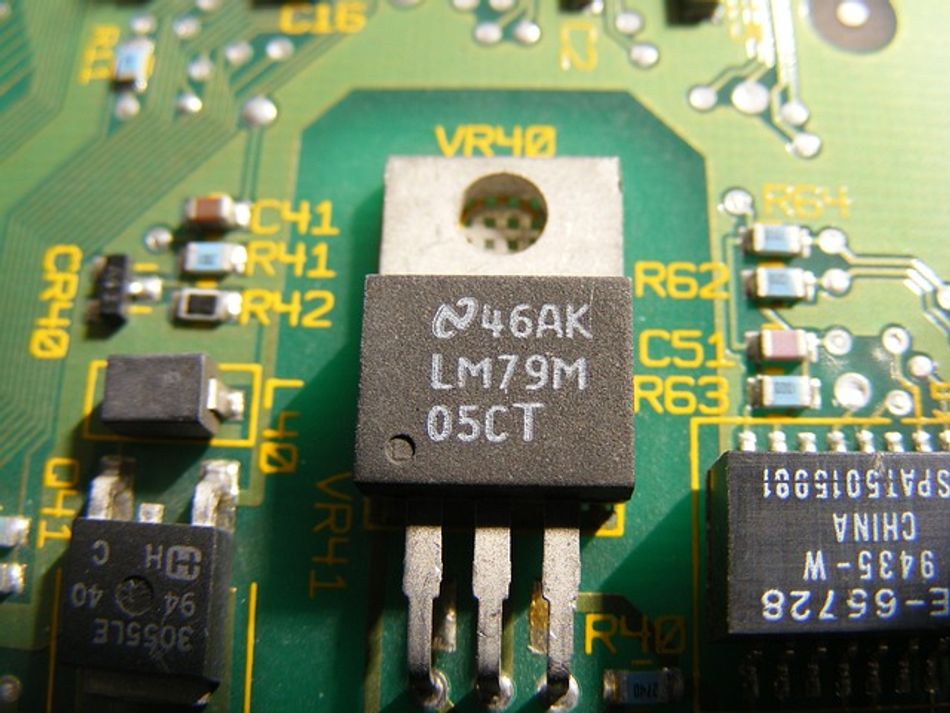
3. Analog ICs – Include operational amplifiers (op-amps), voltage regulators, comparators, and data converters (ADC/DACs).
Example: LM358 op-amp for signal processing, 7805 voltage regulator for stable 5V output
4. Memory ICs – Store data and code (e.g., Flash, EEPROM, DRAM)
5. Interface ICs – Convert communication protocols (e.g., USB, SPI, I2C) and drive peripherals like motors or displays
6. Power Management ICs (PMICs) – Handle power conversion, regulation, and battery management
ICs are typically the most complex components on a PCB, but they simplify the board by offloading a lot of functionality into one package. They come in a variety of packages – from older style through-hole DIP (Dual Inline Package) chips that can be inserted into sockets or soldered, to surface-mount packages like SOIC, QFP, QFN, and BGA (Ball Grid Array) for very high pin counts. Choosing the package may affect how you can prototype or assemble the PCB (DIP packages are easier for breadboarding; BGAs require advanced PCB manufacturing process and routing techniques).
Below are some useful design considerations:
Power Requirements: Supply voltage, current draw, and decoupling capacitors for stability
Input/Output Logic Levels: Compatibility with other PCB components
Thermal Management: Some high-power ICs require heatsinks or PCB copper planes for heat dissipation
Package Type: From through-hole DIP (easy prototyping) to surface-mount QFN and BGA (high-density PCBs)
Modern PCBs integrate a few large ICs surrounded by numerous passive support components, ensuring optimal performance and stability.
Recommended Reading: How is a Microprocessor Different from an Integrated Circuit?
Other Active Components
In addition to diodes, transistors, and ICs, various specialized PCB components enhance circuit functionality:
Optoelectronic Components: Optocouplers (optoisolators) transfer signals between isolated circuits using light (e.g., 4N35 optocoupler)
Thyristors and Triacs: Used for AC power control in dimmers and industrial applications
Sensor ICs: Temperature, motion, and pressure sensors integrate active circuits for precision measurements
Active PCB Board components enable amplification, processing, and control, forming the foundation of all modern electronic circuits. While passive components condition signals and provide stability, active components bring circuits to life by processing, amplifying, and switching electrical signals.
Next, we explore electromechanical components, which bridge the gap between electrical circuits and mechanical functions.
Electromechanical Circuit Board Components
Electromechanical components are those that involve an electrical interaction and physical movement or mechanical action. On a PCB, these typically include things like switches, relays, connectors, and others like potentiometers or mechanical sensors. These parts often form the interface between the electronic circuit and external circuits or users – for example, a connector allows wires or other boards to connect, and a switch allows a user or a mechanical event to change an electrical state.
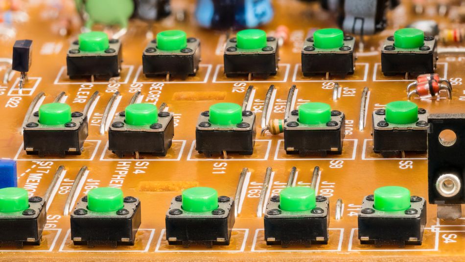
Switches and Push Buttons
A switch is a component that can open or close an electrical circuit by mechanical action, thereby either stopping or allowing current flow.
Toggle Switches: Lever-actuated switches that maintain their state until flipped (commonly used for on/off power switching)
Slide Switches: Small sliding actuators used for selecting power modes or configuration settings
Push Buttons: Momentary switches that only connect a circuit while pressed, commonly used for reset buttons or user input controls
Dip Switches: Dual in-line package switches, which are essentially an array of small toggle switches in a package that can be switched on or off for configuration
Keypad or Keyboard Switches: Tactile switches that detect user keypresses, often used in control panels
Switches are classified by their pole and throw configurations, defining their circuit control complexity:
SPST (Single Pole Single Throw) – A basic on/off switch
SPDT (Single Pole Double Throw) – Routes an input signal to one of two outputs
DPDT (Double Pole Double Throw) – Controls two separate circuits simultaneously
Below are some key design considerations:
Component Placement: User-accessible switches (e.g., power toggles) should be positioned at the edge of the PCB.
Current Rating: Small signal switches handle milliamps, while power switches must support several amps.
Actuation Force & Durability: Pushbuttons and tactile switches should withstand repeated use without degradation.
Recommended Reading: Navigating Network Infrastructure: Patch Panel vs Switch
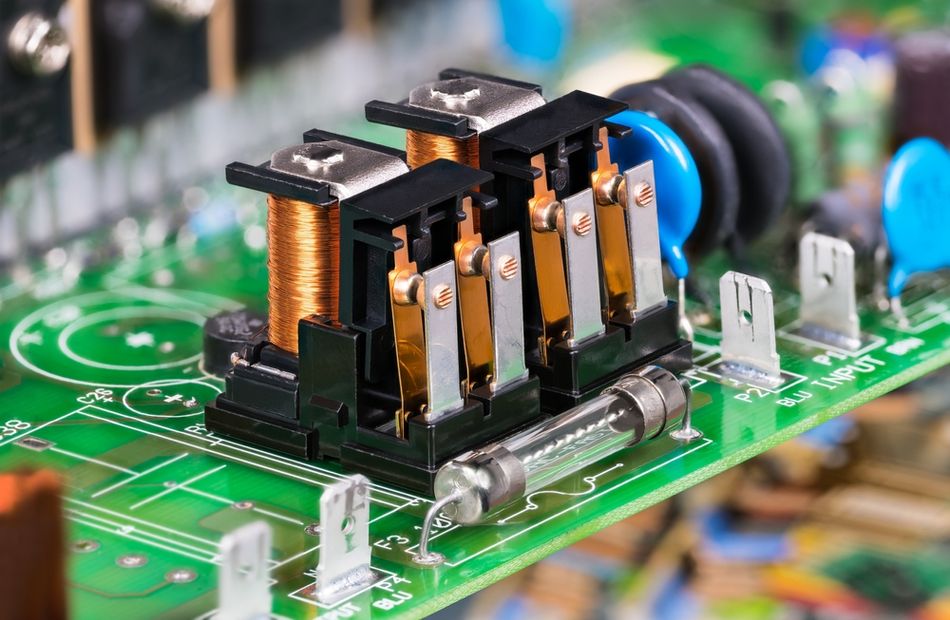
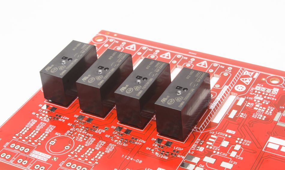
Relays
A relay is an electrically operated switch that uses an electromagnetic coil or solid-state mechanism to control a high-power circuit with a low-power signal. Relays provide galvanic isolation, ensuring safety between control and load circuits.
When a voltage is applied to the coil, it generates a magnetic field that pulls the armature, thereby changing the state of the contacts (opening or closing them). This mechanism allows, for example, a 5 V signal from a microcontroller to switch a 230 V AC load safely, which the microcontroller could not handle directly.
Below are the types of relays:
Electromechanical Relays (EMR) – Use a physical coil and moving contacts. They produce an audible "click" when switching and provide high isolation but have a limited lifespan due to mechanical wear.
Solid-State Relays (SSR) – Use semiconductor devices instead of mechanical contacts, enabling silent, high-speed switching with no physical wear. SSRs are ideal for applications requiring high reliability and frequent switching.
Now, let’s discuss the potential design considerations:
Coil Voltage & Current: Ensure the relay coil voltage (e.g., 5V, 12V) matches the driving circuit
Contact Ratings: Consider voltage/current ratings for load switching (e.g., 10A at 250VAC)
Inductive Loads: For EMRs, a flyback diode is required across the coil to prevent voltage spikes
Snubber Circuits: For high-power SSRs, use snubbers to suppress transient voltages
Relays provide a way to galvanically isolate control and load circuits. They are still widely used in automation, automotive, and appliances, though in purely electronic devices, transistors or MOSFETs often replace relays if the voltages and currents are within what solid-state devices can handle.
Recommended Reading: Contactor vs Relay: Understanding the Differences and Applications
Connectors
Connectors are critical electromechanical components that allow different boards, wires, or devices to connect to the PCB, enabling power or electronic signals to flow on/off the board.
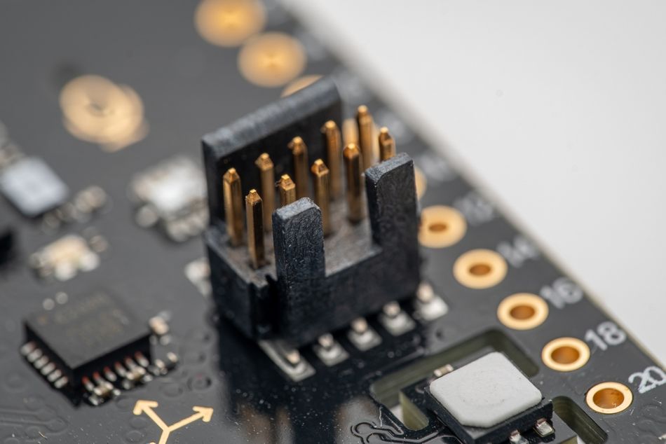
1. Board-to-Wire Connectors
Pin Headers and Dupont Connectors – Used in prototypes and modular PCB designs
Terminal Blocks – Secure bare wires for power and speaker connections
JST Connectors – Compact connectors for battery and sensor connections
Barrel Jacks and USB Ports – Provide power and data connections
2. Board-to-Board Connectors
Card Edge Connectors – Used in expansion cards (e.g., PCIe slots on motherboards)
Mezzanine Connectors – Stack PCBs for compact multi-layer designs
3. I/O Connectors
USB, HDMI, Ethernet (RJ45), Audio Jacks – Facilitate data and power exchange with external devices
IDC Ribbon Connectors – Used for parallel data transmission in industrial systems
4. IC Sockets
Enable easy insertion and removal of integrated circuits without soldering
Connectors often have standardized pin layouts and many are keyed to ensure correct orientation. They are typically one of the largest components on a PCB (physically) because they must be robust enough to handle insertion/removal forces and cable strains.
Let’s go through the design considerations:
Mechanical Strength: Reinforce connectors that undergo frequent plugging/unplugging
Current Capacity: Ensure power connectors can handle the required amperage
High-Speed Signal Integrity: Use controlled impedance routing for high-frequency signals (e.g., HDMI, USB 3.0)
Examples: A simple PCB might have a 2.1mm DC barrel jack for power input, a 2x5 IDC header for programming or debugging, and maybe some screw terminals for connecting out to a sensor or motor. A complex motherboard might have dozens of connectors: USB, network, audio jacks, PCI express slots, etc. Connectors often have reference designators like J1, and J2 (for jacks or connectors) on the silkscreen.
Recommended Reading: 6 Connector Solutions for Servo Motors in Factory Automation Settings
Other Electromechanical Components
Potentiometers/Trimmers: We mentioned these under passives, but they are electromechanical in that they have a knob or screw that moves a wiper across a resistive element to adjust resistance. They often mount on a PCB and either allow user adjustment (e.g., a volume knob potentiometer on an amplifier board) or are meant for one-time calibration by a technician (trimmer pot that you adjust with a screwdriver).
Microphones and Speakers (Buzzers): A microphone (like an electret mic) is an electro-acoustic component – it converts sound to electrical signals and often is considered separately, but it has both electrical and mechanical aspects (a diaphragm). A buzzer or speaker on a PCB converts electrical signals to sound (some buzzers are self-contained with an oscillator). These are often mounted on PCBs for devices that need sound.
Displays: Small LCD or LED displays can be considered electromechanical assemblies. For example, a seven-segment LED display is an array of LEDs (active) in a mechanical frame, and an LCD may have a connector to the PCB. They often interface via connectors or header pins.
Fans, or Motors: Occasionally, a PCB might have a small motor or fan connected (especially on things like PC motherboards, a fan connector is provided, but the fan itself is a separate component). These involve electromechanical principles but are typically off-board or separately mounted due to vibration.
In summary, electromechanical components are all about bridging the gap between electronics and the real world – whether it’s letting a user flip a switch, connecting a power source, or physically moving contacts. They often dictate the form factor of a PCB and need careful attention for reliable operation.
Comparing Component Types: Uses, Advantages, and Trade-offs
Now that we have covered passive, active, and electromechanical components individually, it’s important to understand how these component types differ and how they work together in a design. Each category has its own strengths and limitations, and engineers must choose the right component type for the task at hand.
1. Passive vs Active:
Reliability: Passive components have fewer failure modes since they do not require power. Active components, being more complex, are sensitive to environmental factors (e.g., temperature changes, and power fluctuations).
Functionality: Passive components cannot amplify signals, only attenuate or modify them, while active components provide power gain and signal processing capabilities.
Cost: Passive components are cheaper and widely available, while active components vary in cost—a simple transistor may be inexpensive, but specialized ICs can be costly.
Noise and Distortion: Passive components introduce minimal noise (except thermal noise), while active components can generate noise and distortion if not designed correctly.
Example: A resistor (passive) in a voltage divider reduces a signal, but an operational amplifier (active) boosts a weak signal to a usable level.
2. Active vs Electromechanical (for switching):
Speed and Lifespan: Transistors and MOSFETs can switch in microseconds, whereas mechanical relays take milliseconds and wear out over time. [5]
Power Handling: Electromechanical relays can switch high-voltage AC loads more safely than solid-state switches, which might require extra circuitry for isolation.
Durability: Solid-state switches (transistors, SSRs) do not suffer from contact wear like relays, making them more reliable for frequent switching.
Size: A power MOSFET is smaller and handles fast switching more efficiently than a mechanical relay of a similar power rating.
Example: A MOSFET switch in a DC-DC converter is preferred for fast, efficient power switching, while an electromechanical relay is better suited for galvanic isolation in high-voltage applications.
3. Integration and Size Considerations
ICs Reduce Component Count: Instead of using discrete transistors and resistors, designers often opt for an integrated circuit (IC) that combines multiple functionalities into a single package, saving space and improving reliability.
SMD (Surface-Mount Devices) allow automated assembly and higher component density.
THT (Through-Hole Components) provide stronger mechanical connections (better for connectors, power components, and relays).
Example: A microcontroller (IC) integrates logic functions, memory, and processing power, reducing the need for multiple individual components.
4. Cost and Availability
Passive Components are generally inexpensive and readily available in standard values.
Active Components can range from cheap transistors to expensive microprocessors. Some ICs may face supply chain shortages or long lead times
Electromechanical Components (e.g., connectors, relays) can be among the costliest PCB components, especially for high-speed or rugged designs.
Example: A basic resistor (passive) costs a fraction of a cent, while a custom power management IC (active) may cost several dollars or more.
In practice, a well-designed circuit will use a combination of all these components:
Passive Components to condition signals (filter out noise, set bias points, etc.).
Active Components to perform core operations (compute, amplify, switch) efficiently.
Electromechanical Components to connect to the real world (allow user input, output power, connect wires).
Understanding the interaction is key! For example, a microcontroller (active) uses a crystal oscillator (a passive electromechanical resonator) with capacitors (passive) to create its clock signal; it uses resistors (passive) to set analog reference levels; it might drive a transistor (active) that controls a relay (electromechanical) to turn on a motor; and that relay is connected via a connector (electromechanical) to the motor wiring. Each part is chosen for what it does best.
Recommended Reading: What are Circuit Boards Made Of? An Extensive Guide to Materials and PCB Manufacturing Processes
Conclusion
PCB components create a complex ecosystem, each essential to circuit functionality. Passive components shape signals, set voltages, and store energy. Active components amplify, switch, and process signals, enabling advanced operations. Electromechanical components provide physical interaction and high-power control, bridging electronics with the external world. Future trends focus on miniaturization and integration, with multi-function ICs reducing discrete components. Advanced packaging continues shrinking passives, while modular solutions like system-in-package (SiP) and wireless modules simplify PCB design. However, fundamental building blocks—resistors, capacitors, transistors—remain indispensable, whether discrete or integrated within larger components.
Frequently Asked Questions (FAQs)
Q: What is the difference between passive and active PCB components?
A: Passive components do not require power and only condition signals by storing, filtering, or dissipating energy (e.g., resistors, capacitors, inductors). Active components require power and can amplify, switch, or process signals (e.g., transistors, diodes, ICs). Passive components modify signals, while active components control circuit behavior.
Q: Why are resistors and capacitors so commonly used on every PCB?
A: Resistors control current and divide voltages, essential for biasing circuits and setting logic levels. Capacitors store charge, smooth power fluctuations, and filter noise. They enable stability, signal conditioning, and proper circuit operation. Virtually every PCB requires them for voltage regulation, power decoupling, and filtering unwanted signals in electronic designs.
Q: What are common examples of electromechanical components on a PCB, and when are they used?
A: Connectors provide external power and signal connections, switches enable user input, and relays switch high-power loads. These components are used for interfacing with external hardware, controlling circuits manually, or isolating high-voltage and low-voltage sections in power control and automation applications.
Q: How do I decide between using a transistor (solid-state) vs a relay for switching on my PCB?
A: Use a transistor for fast, silent switching in low-voltage DC circuits requiring efficiency and reliability. Use a relay when switching high voltage, high power, or requiring electrical isolation. Relays handle AC loads better but are slower and bulkier. Solid-state relays (SSRs) provide an efficient, hybrid alternative.
References
[1] Wikipedia. Ohm’s Law [Cited 2025 March 20] Available at: Link
[2] IOSR. Concept And Working Of Different Types Of Fuses [Cited 2025 March 20] Available at: Link
[3] Wevolver. How Does a Diode Work: Unraveling the Heart of Electronic Control [Cited 2025 March 20] Available at: Link
[4] Moniteur. What is the Difference Between, SPST, SPDT and DPDT? [Cited 2025 March 18] Available at: Link
[5] NTChip. The Difference Between Relay and MOSFET [Cited 2025 March 18] Available at: Link
Table of Contents
IntroductionPassive PCB ComponentsResistorsCapacitorsInductorsOther Passive ComponentsActive PCB ComponentsDiodes (and LEDs)TransistorsIntegrated Circuits (ICs)Other Active ComponentsElectromechanical Circuit Board ComponentsSwitches and Push ButtonsRelaysConnectorsOther Electromechanical ComponentsComparing Component Types: Uses, Advantages, and Trade-offsConclusionFrequently Asked Questions (FAQs)References