What is an Open Circuit: A Deep Dive for Engineers
A comprehensive exploration of open circuits, detailing their characteristics, detection methods, and the pivotal role they play in modern engineering systems.

03 May, 2024. 10 minutes read

Introduction
In electrical and electronic engineering, an open circuit signifies a break in continuity, halting the flow of electric current. This critical concept is not only foundational to the field but also pivotal in troubleshooting and system optimization, demanding a keen understanding from engineering professionals.
Understanding open circuits is an important aspect of addressing electrical problems. The troubleshooting and rectification of open circuits can help regain functionality in electrical and electronic devices and maintain the smooth operation of electrical systems which proves cost-effective, especially for industrial applications. Moreover, alongside troubleshooting, grasping methods to prevent open circuits is paramount. Consistent upkeep, employing correct wiring techniques, referencing electrical schematics, and utilizing quality components aid in minimizing the occurrence of open circuits, ensuring the durability of your electrical systems.
This post will explore the basics of open circuits such as:
The definition and causes
Open circuit resistance
How open circuits are different from short circuits
Detection, advancements, and applications of open circuits
What is an Open Circuit?
An open circuit refers to an electrical circuit where current fails to flow. Current can only move through a circuit if it encounters an unbroken path, referred to as a "closed circuit." When there's a disruption anywhere in the circuit, it becomes an open circuit, preventing current flow.
In an open circuit, the two terminals become disconnected, resulting in a break in circuit continuity. Despite the inability of current to traverse the circuit, there exists a voltage drop between two points within the circuit.
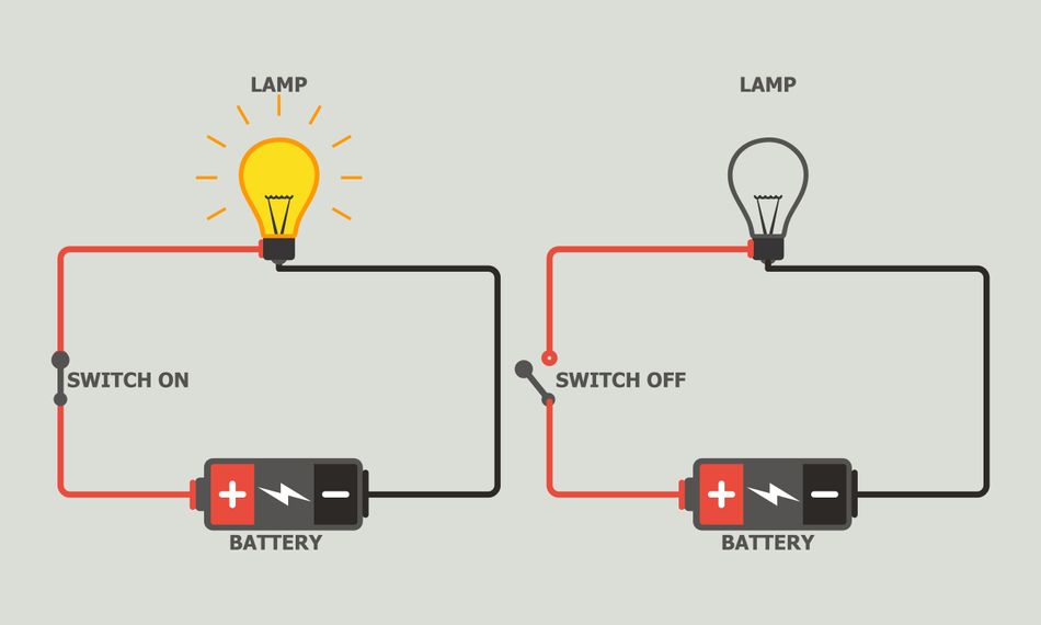
For instance, consider an electrical schematic containing a battery, switch, wires, and a lightbulb. The switch position decides whether the two terminals or nodes allow or stop the current from traveling through the circuit.
Missing signals or power - When a circuit path is unexpectedly interrupted, the intended signal or power can't reach its destination.
Sudden breaks - Internal damage within a circuit, like a broken wire or a faulty switch, can also lead to an open circuit.
Power outages - A broader example is a power failure, which essentially creates an open circuit for an entire electrical system.
Understanding Open Circuits
The Anatomy of an Open Circuit
An open circuit is characterized by a break or gap in a circuit that prevents the flow of electrical current. This interruption is generally mechanical and can occur due to various factors such as a broken wire, a switch being in the "off" position, or a blown fuse. In electronic circuits, the interruption can also occur due to biasing and controlled current flow as in the case of diodes and transistors.
Understanding the technical specifications of circuit components and the physics behind electricity is essential to grasp how open circuits form and their effect on the overall circuit behavior. Open circuits result in an infinite resistance, zero current flow, and the potential difference across the open, reflecting the source voltage.
Open Circuit Resistance
An open circuit is defined by the absence of a complete path for current to flow, which theoretically results in infinite resistance. This fundamental principle has profound implications for the operation and safety of electrical systems.
Infinite Resistance Explained - When a circuit is open, the electrical path is broken, and no current can flow, regardless of the applied voltage. This is because current requires a closed loop to travel, and an open circuit disrupts this loop. Essentially, it acts as an infinite resistance, supported by Ohm’s Law:
I = V/R
At any given voltage, an infinite resistance yields Zero current.
Engineering Implications - In real-world applications, open circuits can cause system malfunctions, from simple lighting fixtures to complex industrial machinery. For instance, consider a smoke detector circuit placed in an industrial setup. If the wire connecting to the sensor somehow disconnects, the sensor will not receive the desired voltages and hence will not detect any smoke or fire. Such a malfunction could lead to serious casualties. Typically, it can happen due to overheating wires, corrosion, or loose connections. Hence, implementing safeguards such as circuit breakers and fuses is essential to avoid potential failures and ensure operational continuity.
Causes of Open Circuits
There are three main causes of open circuits:
Component Failure - Breakage, damage, or loose connections
External Factors - Corrosion, power outages
Human Error - Accidental disconnections, lack of monitoring
Component Failure
Failure in electrical conductors and components is perhaps the major cause of open circuits. These failures include:
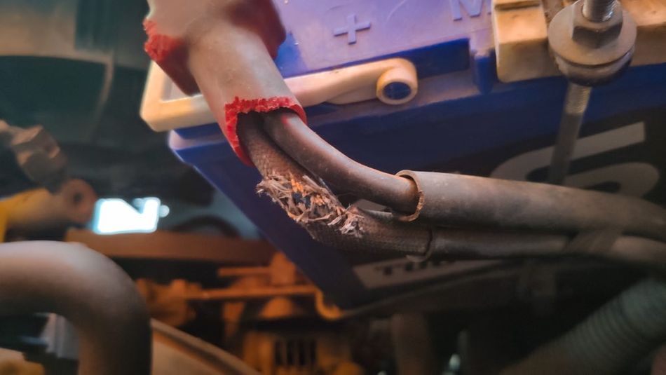
Broken Wires - Physical damage to wires, such as cuts, frays, or burnt sections, can create an open circuit. This can be caused by wear and tear, overheating, or external factors like rodent chewing.
Loose connections - Terminals that are not securely fastened can create an open circuit if they don't make proper contact. This could be due to loose screws, vibration, or corrosion.
Burnt-out Components - Fuses, resistors, or other electronic components can fail due to overloading or overheating, creating an open circuit within the device.
Switch Malfunction - A faulty switch that gets stuck in the open position can disrupt the circuit path.
External Factors
External factors refer to environmental issues or supply problems, such as:
Power Outages - A broader open circuit scenario occurs during a power outage. The entire electrical supply is interrupted, preventing current flow to all connected devices.
Corrosion - Over time, metal components within a circuit can corrode, forming an insulating layer that disrupts the flow of electricity.
Human Error
Negligence from operators can also lead to open circuits.
Accidental Disconnection - Unplugging a power cord or accidentally knocking loose a wire connection can create an open circuit.
Incorrect Installation - Improper wiring during circuit installation can lead to open circuits if connections are not made correctly.
Open Circuits in Electronics
In electronics, the flow of current is typically controlled by semiconductor devices. For instance, diodes and transistors control the flow of current by acting as a switch, essentially opening and closing the circuit.
Transistor as an Open Circuit
Transistors have three primary operating modes:
Active
Saturation
Cut-off
Each mode depends on the voltage applied to the base (control terminal) relative to the emitter and collector (current flow terminals).
In cut-off mode, the transistor acts like an open circuit. This happens when the Base voltage (Vbe) is lower than both the emitter voltage (Vbe) and collector voltage (Vce). This creates a depletion region around the base that significantly reduces the current flow between the collector and emitter, such that:
Ib = 0
Essentially, the transistor becomes a high-resistance path between the collector and emitter, blocking any significant current, a behavior similar to an open circuit in a regular circuit where a break in the connection prevents current flow.
This behavior of transistors is utilized in digital circuits, where transistors act as switches. When in cut-off mode, the transistor acts as an "off" switch, blocking current flow and representing a logical "0" state.
Further Reading: Understanding Transistors: What They Are and How They Work
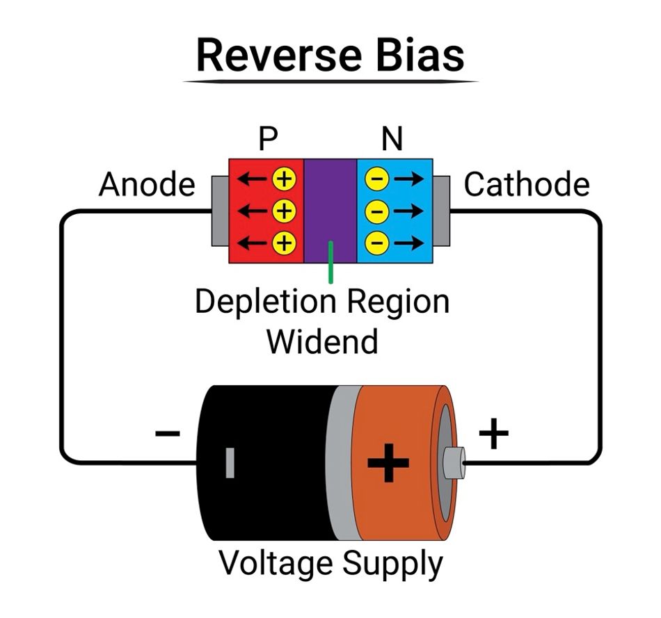
Diode as an Open Circuit
A reverse-biased diode is a good example of an open circuit. In reverse bias, the negative terminal of the diode is at a higher potential than the positive terminal. As a result, the internal depletion region continues to expand and no electrons can cross the potential barrier. Hence, it seizes the current flow, resulting in zero current across the diode.
Further Reading: Forward Bias, Reverse Bias and their effects on Diodes
Open Circuit Vs Short Circuit
Open and short circuits represent two primary types of electrical faults, each with distinct characteristics and implications for electrical systems.
Feature | Open Circuit | Short Circuit |
Definition | Identified by a break in continuity of the electrical path | Formation of an unintended low-resistance path between two conductive parts of a circuit. |
Electrical Characteristics | Infinite Resistance and Zero Current Flow | Minimal resistance and high current flow |
Consequences | Device failure | Damaged device, electrical fires |
Identifying Open Circuits in Electrical Systems
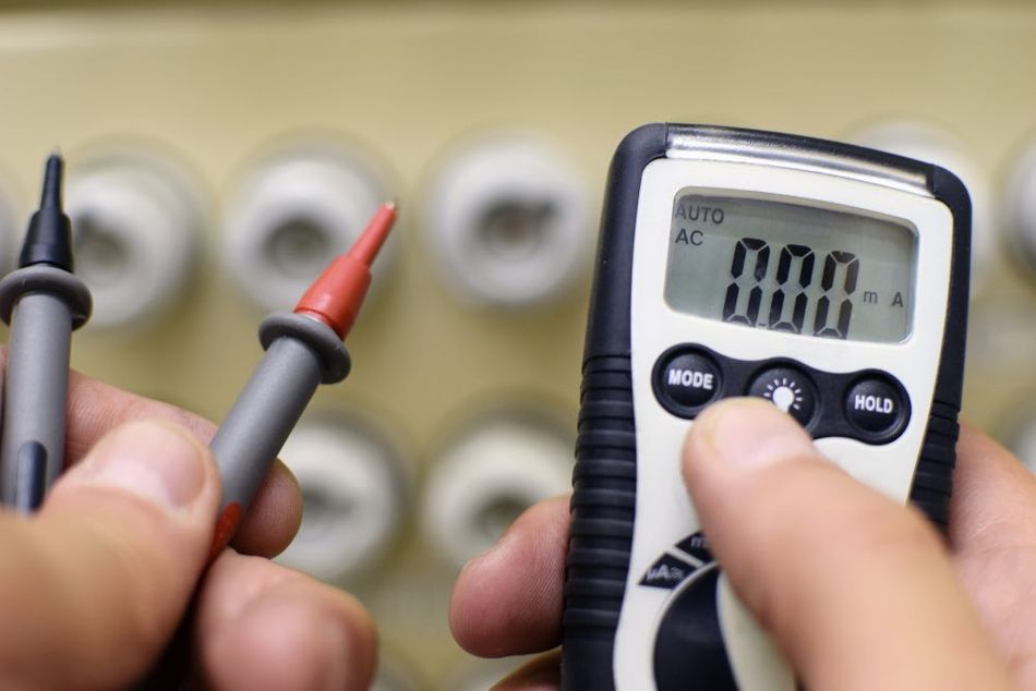
Effective identification of open circuits hinges on recognizing key symptoms and employing advanced diagnostic tools. Key indicators of an open circuit include sudden power failures, inactive components, and atypical readings from testing instruments.
Visual Inspection - Inspect for overt signs of wear, disconnections, or damage in wiring and circuit components.
Multimeter Testing - Utilize a multimeter to check for continuity by measuring voltage and resistance at various points along the circuit.
Oscilloscope Analysis - Deploy an oscilloscope to detect irregularities in the electrical waveform, which often signify disruptions in current flow.
These targeted techniques enable precise localization and swift resolution of open circuits, ensuring system reliability and performance.
Innovations in Open Circuit Detection and Management
Cutting-edge tools for Diagnosing Open Circuits
The landscape of electrical diagnostics has been transformed by a suite of sophisticated tools that enhance precision and streamline troubleshooting processes. These instruments are pivotal in detecting and analyzing open circuits:
Advanced Digital Multimeters - These devices offer high-resolution measurements of voltage, resistance, and continuity, quickly pinpointing areas of discontinuity in circuits.
High-Definition Oscilloscopes - Essential for visualizing electrical signals, oscilloscopes provide a dynamic view of current flow and interruptions, facilitating rapid diagnosis.
Thermal Imaging Cameras - By capturing heat patterns, these cameras identify hot spots caused by electrical resistance at open points, allowing for non-invasive inspections.
Automated Circuit Analyzers - Combining several diagnostic functions, these analyzers deliver detailed evaluations of circuit integrity, identifying faults with precision.
Advancements in Automated Open Circuit Resolution
The advent of artificial intelligence (AI) and machine learning (ML) technologies has significantly advanced the capabilities of automated systems in detecting and resolving open circuits. These systems utilize complex algorithms to efficiently manage and rectify circuit issues:
AI-Driven Diagnostic Tools - Utilizing neural networks and pattern recognition, these tools analyze vast amounts of circuit data to detect anomalies indicative of open circuits, far beyond human error rates.
ML-Based Automated Repair Systems - These systems apply predictive models to preemptively identify potential faults and perform real-time repairs or adjustments, drastically minimizing system downtime.
Recommended reading: Open Circuit vs. Short Circuit
The Role of Open Circuits in Safety and System Reliability
Open circuits can critically undermine the safety and reliability of electrical systems, with far-reaching consequences:
System Failures - An open circuit in a control system can halt production lines, trigger outages in power distribution networks, and disrupt communication infrastructure.
Safety Hazards - In life-critical systems like medical devices or transportation controls, open circuits can compromise safety features, endangering lives.
Operational Inefficiencies - Chronic open circuits in industrial equipment can lead to increased wear and tear, necessitating frequent repairs and leading to substantial economic impact.
Here are some real-world applications of open-circuits.
Safety On, Current Off - On/off switches and safety devices like fuses/breakers create open circuits in "off" positions or overloads, preventing device operation/damage and isolating faults.
Logic & Sensors - Openings with Purpose: Logic gates use open circuits as inputs, while some sensors (like pushbuttons or light sensors) create open/closed circuits depending on the measured quantity.
Troubleshooting Through Breaks - Technicians identify open circuits (breaks/disconnections) by measuring voltage or continuity, aiding in problem diagnosis.
Circuit Protection - Fuses and circuit breakers act like automatic switches, creating open circuits during overloads or short circuits. This stops excessive current flow that could damage components or start fires.
Sensor Detection - Some sensors function by opening or closing circuits based on what they detect. A pushbutton switch is an open circuit when unpressed, while a light sensor might be open in darkness but closed with light present.
Incorporating rigorous open circuit detection into preventive maintenance protocols is essential, particularly in high-stakes environments such as power generation facilities, mass transit systems, and manufacturing plants, to ensure continuous and safe operation.
Overcoming Technical Hurdles in Open Circuit Analysis
Addressing the advanced technical challenges of open circuit analysis in complex systems involves a nuanced understanding of system architecture and the integration of cutting-edge diagnostic technologies.
Complex System Interdependencies - Identifying the root cause of an open circuit in systems with interconnected components often requires the use of advanced simulation software that can model and predict system behavior under various scenarios.
Microelectronic Components - The repair of open circuits in microelectronics demands precision tools and techniques, such as micro-soldering and circuit printing, to restore functionality without impacting adjacent components.
Emerging Technologies - Implementing AI-driven diagnostics and machine learning algorithms can drastically improve the efficiency and accuracy of fault detection and resolution processes, reducing downtime and maintenance costs.
These targeted strategies are essential for maintaining the integrity and functionality of modern electronic systems, ensuring they operate reliably and efficiently.
Conclusion
This article has explored the critical aspects of open circuits, from their basic definitions and symptoms to the advanced tools and strategies used for their detection and management. Understanding and effectively managing open circuits is essential for maintaining the safety, reliability, and efficiency of electrical systems in various engineering fields.
FAQs
1. What are the most common causes of open circuits in electrical systems?
Open circuits typically occur due to broken wires, loose connections, or failed components within the circuit.
2. How do open circuits differ from short circuits and why is the distinction important?
An open circuit is a break in the continuity that stops the current flow, whereas a short circuit is a direct path between two points in a circuit that allows current to flow freely, bypassing the intended path. Distinguishing between them is crucial for proper troubleshooting and repair.
3. What are the best practices for preventing open circuits in new designs?
Implementing thorough design reviews, using quality components, ensuring proper installation practices, and conducting regular maintenance checks are effective strategies to prevent open circuits.
4. How Do electronic components simulate an open circuit?
Electronic devices like diodes and transistors act as switches which enables them to work as open or closed circuits. When the diode is reverse-biased, it becomes an open circuit. Likewise, when the transistor operates in the cut-off region, it’s an open circuit.
References
Open Circuit: What is it? (And How Does it Differ To a Short Circuit) | Electrical4U
Open Circuit vs Short Circuit: What's the Key Difference? (galvinpower.org)
Open Circuit in a Circuit: What Is It and Is It Dangerous - TechSparks (tech-sparks.com)
Table of Contents
IntroductionWhat is an Open Circuit?Understanding Open CircuitsThe Anatomy of an Open CircuitOpen Circuit ResistanceCauses of Open CircuitsComponent FailureExternal FactorsHuman ErrorOpen Circuits in ElectronicsTransistor as an Open CircuitDiode as an Open CircuitOpen Circuit Vs Short CircuitIdentifying Open Circuits in Electrical SystemsInnovations in Open Circuit Detection and ManagementCutting-edge tools for Diagnosing Open CircuitsAdvancements in Automated Open Circuit ResolutionThe Role of Open Circuits in Safety and System ReliabilityOvercoming Technical Hurdles in Open Circuit AnalysisConclusionFAQs 1. What are the most common causes of open circuits in electrical systems? 2. How do open circuits differ from short circuits and why is the distinction important? 3. What are the best practices for preventing open circuits in new designs? 4. How Do electronic components simulate an open circuit?References