Why Are Circuit Boards Green? Unraveling the Mystery Behind the Iconic Color
This article delves into the history and science behind the green color of circuit boards, shedding light on the reasons and advantages that have kept it at the forefront of electronics manufacturing.

21 Oct, 2024. 21 min read
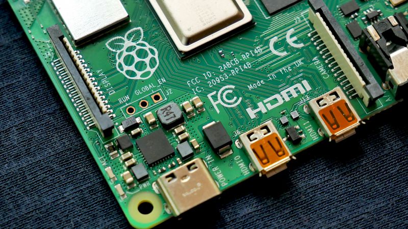
Green Printed Circuit Board - Raspberry Pi
Introduction
Circuit boards are the backbone of modern electronics, serving as the foundation for countless devices that power our digital world. These intricate networks of conductive pathways and components enable the flow of electricity and information, bringing life to everything from smartphones to satellites. Once you see inside any electronic device, you'll likely wonder… Why are circuit boards green?
The dominance of green in the world of printed circuit boards (PCBs) is no accident! It's a fascinating story that binds historical coincidences, practical benefits, and technological advancements together. The green color mainly comes from the solder mask, which helps protect the delicate copper circuits underneath from air and errors during soldering. So, if anyone asks, why are circuit boards green, remember that we've to uncover a mix of history, practicality, and industry standards.
Still curious about, why are circuit boards green? Let’s discover the practical reasons behind this iconic color choice in electronic design!
The Emerald Enigma: Decoding the Green Standard
The prevalence of green circuit boards is rooted in a combination of historical coincidence and practical advantages. In the early days of printed circuit board (PCB) manufacturing, the color green emerged as the default choice for solder masks. It’s basically a protective layer applied to the copper traces of the board. This solder mask serves multiple crucial functions: it prevents oxidation, provides insulation, and protects against solder bridges during the assembly process.

The green color of the solder mask is primarily derived from its epoxy resin composition, which naturally tends towards a green hue when cured. The electronics industry rapidly expanded in the 1960s and 1970s. This green epoxy-based solder mask became the most readily available and cost-effective option for manufacturers. Over time, several factors solidified the position of green color as the industry standard:
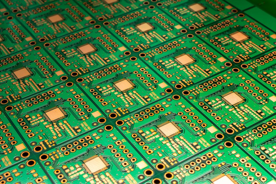
Visibility: Green provides excellent contrast against copper traces and other board components, facilitating easier visual inspection and quality control.
Cost Effectiveness: The widespread adoption of green solder masks led to economies of scale, making it the most affordable option.
Heat Resistance: Green epoxy-based solder masks demonstrate superior heat resistance compared to other available colors at the time.
Familiarity: As green became usual, engineers and technicians grew accustomed to working with this color, further adding to its dominance.
The perception of human eye to green wavelengths plays a significant role in the color effectiveness of circuit board applications. The human visual system is most sensitive to green light, particularly in the 495-570 nanometer range. [1] This high sensitivity allows for better detection of precise variations in shade and texture, crucial for identifying defects or irregularities during the inspection process.
Furthermore, the green color of circuit boards offers practical benefits in terms of light reflection and absorption. Green surfaces reflect a moderate amount of light while absorbing enough to reduce glare, creating an optimal balance for visual examination. This characteristic is mostly useful in manufacturing environments where consistent and accurate visual inspection is essential for ensuring the reliability and functionality of electronic components.
The Accidental Green Revolution
The emergence of green as the standard color for circuit boards was not a deliberate choice but rather a sudden outcome of early manufacturing processes. In the 1960s, manufacturers needed a reliable way to protect the copper traces on the circuit boards from oxidation and short circuits. Epoxy-based resins emerged as an ideal solution due to their excellent insulating properties and durability.
The green hue that has become synonymous with PCBs was an unintended consequence of the chemical composition of these early epoxy resins. The base resin, typically a bisphenol A epoxy, would often have a slight yellow tint. When combined with hardeners and other additives necessary for the solder mask's functionality, the resulting mixture took on a distinctive green color upon curing.
Early manufacturers quickly realized that this green epoxy formulation offered several advantages. It was not only cost-effective to produce but also readily available from multiple suppliers. The chronological events that led to green becoming the dominant color in PCB manufacturing are outlined as:
Late 1950s: Introduction of the first epoxy-based solder masks for PCBs.
Early 1960s: Discovery that certain epoxy formulations naturally cure to a green color.
Mid-1960s: Recognition of green's superior contrast properties for visual inspection.
Late 1960s: Widespread adoption of green solder mask by major electronics manufacturers.
1970s: Standardization of green as the default color due to economies of scale in production.
1980s: Establishment of green as the industry standard, with other colors considered speciality options.
1990s-2000s: Continued dominance of green despite the introduction of alternative colors, due to familiarity and established manufacturing processes.
The accidental green revolution in PCB manufacturing demonstrates how unplanned factors can sometimes lead to industry-wide standards. The combination of practical benefits, cost-effectiveness, and simple familiarity has kept green at the forefront of PCB production for decades.
The Science of Solder Mask
Solder mask serves as a protective layer in PCB that insulates and shields the copper traces from environmental factors and potential short circuits. The composition of solder masks typically includes epoxy resins, hardeners, and various additives that contribute to their performance characteristics.
The application process of solder masks involves several steps:
The liquid solder mask is applied to the PCB surface through screen printing or spraying techniques.
The board then undergoes a pre-curing process, where it's exposed to ultraviolet light to partially harden the mask.
This is followed by the imaging process, where areas that need to remain uncovered (such as component pads and vias) are exposed to UV light through a photomask.
The unexposed areas are then washed away, leaving a precise pattern of solder mask on the board.
Finally, the PCB undergoes a thermal curing process to fully harden the solder mask.
Green solder mask, the industry standard, owes its effectiveness to its unique chemical properties. The green color is typically achieved through the addition of chromium oxide or organic pigments to the epoxy resin base. [2] These additives not only provide the characteristic green hue but also contribute to the durability and heat resistance of the mask. The molecular structure of these pigments allows for excellent adhesion to the PCB substrate while maintaining flexibility to withstand thermal stress during soldering processes.
The effectiveness of the green solder mask is further enhanced by its optical properties. The specific wavelength of green light reflected by the mask provides optimal contrast against copper traces and other board components. This facilitates easier visual inspection and quality control processes.
Let’s get into the comparative advantages of green solder mask, and see the properties of Green different solder mask colors:
| Color | Heat Resistance (°C) | Visibility (1-10) | Cost (per sqm) | Durability Rating (1-10) |
| Green | 150 | 9 | $0.10 | 8 |
| Red | 130 | 7 | $0.12 | 7 |
| Blue | 140 | 8 | $0.12 | 6 |
| Black | 160 | 6 | $0.15 | 9 |
| White | 120 | 5 | $0.11 | 5 |
Green solder mask offers an optimal balance of heat resistance, visibility, cost-effectiveness, and durability. Its high visibility rating of 9 out of 10 underscores its superiority in facilitating visual inspection processes. While the black solder mask exhibits slightly higher heat resistance and durability, the lower cost and superior visibility of the green mask make it an optimum choice.
Recommended Reading: PCB Solder Mask: Everything You Need to Know
Beyond the Green: The Color Spectrum of Circuit Boards
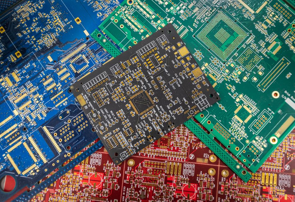
While green has long been the standard color for printed circuit boards (PCBs), the industry has evolved to embrace a diverse palette of colors. This shift is driven by various factors, including specific industry requirements, aesthetic considerations, and functional advantages offered by different colors.
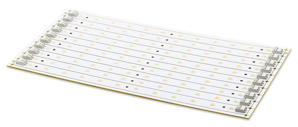
The choice of PCB color is not only cosmetic; it can significantly impact the performance, manufacturability, and end-use application of the board. For instance, white solder masks are often used in LED applications to enhance light reflection. However, black solder mask is preferred in aerospace and defence industries for its heat dissipation properties. [3]
Here's a table outlining different PCB colors and their common applications or industries:
| Color | Common Applications/Industries |
| Green | General Electronics, Consumer Products |
| Red | Automotive, High Temperature Applications |
| Blue | Aerospace, Medical Devices |
| White | LED Lighting, Consumer Electronics with Aesthetic requirements |
| Black | Aerospace, Defense, High-End Audio equipment |
| Yellow | Flexible Circuits, Automotive |
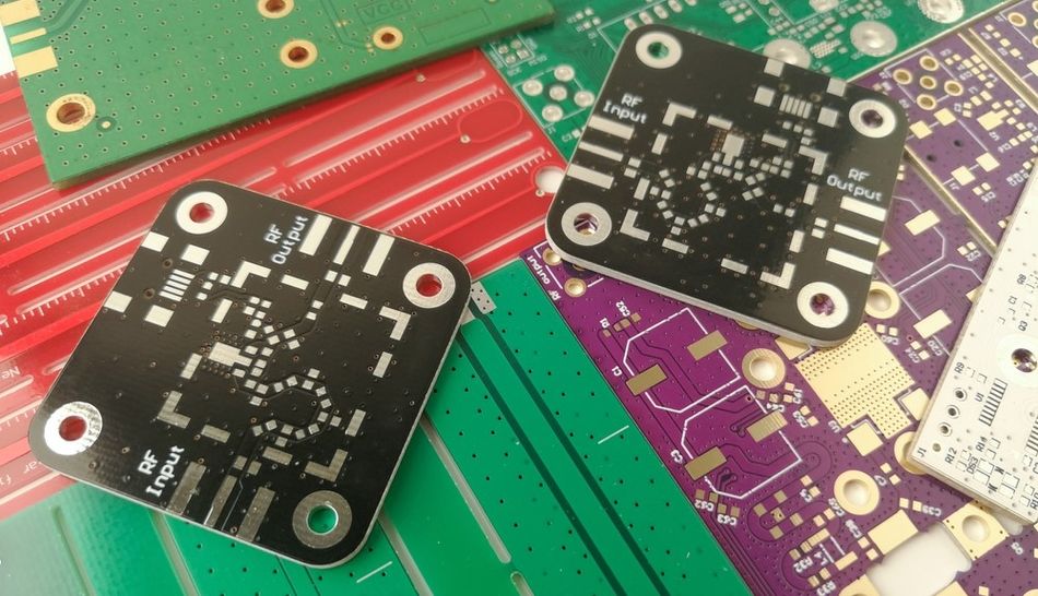
| Purple | Telecommunications, RF Applications |
The color of a PCB can affect its performance in several ways. For example, darker colors like black and blue tend to absorb more heat, which can be beneficial in applications where thermal management is crucial. Conversely, lighter colors like white reflect more light, which is advantageous in LED applications where maximizing light output is essential.
From an aesthetic perspective, the color of a PCB can play a significant role in product design. In consumer electronics, where the PCB might be visible, colors can be chosen to complement the overall product aesthetics. This is particularly relevant in transparent or translucent device casings where the PCB becomes part of the visual appeal.
Functionality is another key consideration in PCB color selection. Some colors provide better contrast for visual inspection, which is crucial in quality control processes. For instance, white boards offer excellent contrast for solder joints and component markings. This makes defect detection easier during manual inspection.
The choice of color can also impact the board's functionality in terms of signal integrity. While the effect is generally minimal, studies suggest that certain pigments used in solder masks can affect the dielectric properties of the board. This potentially influences high-frequency signal transmission.
In specialized applications, such as in the medical field, specific colors might be chosen for their ability to absorb or reflect certain wavelengths of light. This can be crucial in devices that rely on optical sensors or in environments where light interference needs to be minimized.
The decision to use a non-green PCB typically involves a careful balance of functional requirements, aesthetic considerations, and cost factors.
The Rainbow of Functionality
The spectrum of colors used in printed circuit boards (PCBs) extends far beyond the traditional green, each hue serving specific purposes in various industries and applications. This diversification of colors is not only aesthetic but deeply rooted in functional requirements and industry-specific needs.
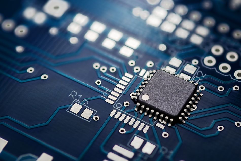
In the aerospace industry, blue PCBs have gained prominence due to their ability to withstand extreme temperatures and harsh environmental conditions. The blue solder mask often contains additives that enhance its resistance to thermal cycling and moisture, crucial factors in aviation electronics. For instance, the avionics systems in commercial aircraft frequently utilize blue PCBs to ensure reliability in high-altitude operations.
The use of alternative colors in PCBs comes with both advantages and disadvantages:
Advantages:
Enhanced visibility for specific applications (e.g., white for LED boards)
Improved thermal management in certain colors (e.g., black for heat absorption)
Easier visual differentiation in complex systems
Potential for reduced eye strain during manual inspection processes
Aesthetic appeal in consumer products with visible PCBs
Disadvantages:
Higher production costs due to lower volume and specialized materials
Potential for reduced contrast in visual inspection for some color combinations
Limited availability of certain colors from PCB manufacturers
Possible impact on signal integrity in high-frequency applications
Increased lead times for non-standard color orders
The choice of PCB color ultimately depends on a careful balance of functional requirements, industry standards, and cost considerations. As technology advances, the palette of PCB colors continues to expand. This offers engineers and designers more options to optimize their designs for specific applications and environments.
Recommended Reading: Types of Printed Circuit Boards: A Comprehensive Guide
From Copper to Color: The PCB Manufacturing Process
The journey from raw materials to a fully functional, colored printed circuit board (PCB) involves a complex series of steps. The process combines precision engineering with chemical processes, resulting in the intricate boards that power our electronic devices.
Let’s go through the PCB manufacturing process, from copper to color:
Design: The process begins with creating a detailed PCB layout using Computer-Aided Design (CAD) software. This step defines the board's layers, traces, pads, and component placements.
Printing: The design is transferred onto a specialized film, which serves as a template for the subsequent steps. This film is crucial for accurately reproducing the intricate patterns on the PCB.
Lamination: Copper foil is bonded to the substrate material, typically FR-4 (a composite of woven fiberglass cloth and epoxy resin). This lamination process uses heat and pressure to create a strong bond between the copper and the substrate.
Etching: The board undergoes a chemical etching process to remove unwanted copper, leaving only the desired conductive pathways. This step is critical in defining the electrical characteristics of circuit board.
Drilling: Holes are created for component leads and vias (connections between layers). Precision drilling ensures proper component placement and inter-layer connectivity.
Plating: A thin layer of copper is applied to the drilled holes, ensuring electrical conductivity throughout the board's layers. This step is essential for multi-layer PCBs.
Solder Mask Application: This is where color enters the process. A layer of solder mask, typically epoxy or polyimide resin, is applied to the board. The traditional green color comes from adding pigments to this resin.
Surface Finish: Various surface finishes like HASL (Hot Air Solder Leveling), ENIG (Electroless Nickel Immersion Gold), or OSP (Organic Solderability Preservative) are applied to exposed copper areas. These finishes protect the copper and enhance solderability.
Silkscreen: Identification marks, component designators, and logos are printed onto the board using glass epoxy or urethane-based inks. The color of this silkscreen is often white or yellow for contrast against the solder mask.
Testing: Electrical tests are performed to ensure the board functions as designed. This step may include both automated and manual inspections.
Shipment: The finished PCBs are packaged and shipped for component assembly or to the end customer.
The color application, primarily through the solder mask, is more than aesthetic. It affects the visibility of the board during inspection. Its heat absorption and dissipation properties can even influence the performance of the board in specific applications.
Quality Control: The Green Advantage
In the realm of printed circuit board (PCB) manufacturing, quality control is necessary to ensure the reliability and functionality of electronic devices. The PCBs green color plays a crucial role in this process, offering significant advantages in visual inspection and defect detection.
The green solder mask provides an optimal background for visual inspection due to its high contrast with other board components. The specific shade of green used in PCBs, typically around 550 nanometers in wavelength, falls within the peak sensitivity range of human photopic vision. This alignment enhances the ability of quality control personnel to identify defects quickly and accurately during manual inspections.

In automated optical inspection (AOI) systems, the green solder mask serves as a consistent reference point. These systems use sophisticated image processing algorithms to compare the inspected board against a "golden" reference image. [4] The green background provides a stable baseline for color-based image analysis. This allows for more accurate detection of variations in solder joint quality, component placement, and trace integrity.
The contrast provided by the green solder mask is particularly useful in the following technical aspects of defect detection:
Solder Joint Analysis: The reflective properties of solder against the matte green background allow for easy identification of insufficient or excessive solder.
Trace Integrity Verification: Breaks or thinning in copper traces are more visible against the uniform green background.
Component Polarity Checking: The orientation of components, often marked in white or yellow, is clearly discernible against the green substrate.
Foreign Object Detection: Contaminants or debris on the board surface stand out more prominently on the green background.
The effectiveness of green color in quality control extends beyond visual inspection. In X-ray inspection systems, used for examining hidden solder joints in ball grid arrays (BGAs) or other complex packages, the green solder mask provides a consistent background density. This uniformity enhances the contrast of the X-ray image, making it easier to identify voids, insufficient solder, or other internal defects.
Furthermore, the interaction of green solder masks with different wavelengths of light is used in advanced inspection techniques. For instance, some systems use UV light to induce fluorescence in the solder mask. This can reveal microcracks or other surface imperfections that might be invisible under normal lighting conditions.
Recommended Reading: PCB Manufacturing Process: A Comprehensive Guide to Understanding and Mastering the Techniques
The Green Edge: Advantages of Emerald Circuit Boards
The prevalence of green as the standard color for printed circuit boards (PCBs) is rooted in a combination of historical precedent and practical advantages. Green solder mask offers a unique set of benefits that have solidified its position as the industry standard in electronics manufacturing.
Key benefits of using green as the standard color for circuit boards include:
Optimal Contrast: Green provides excellent contrast against copper traces and other board components, facilitating easier visual inspection and quality control.
Reduced Eye Strain: The human eye is most sensitive to green wavelengths, making it easier for inspectors to work for extended periods without fatigue.
Cost-Effectiveness: Due to its widespread use, a green solder mask is often the most economical option for PCB production.
Consistency in Manufacturing: The standardization of green boards allows for more consistent production processes across the industry.
Enhanced Defect Detection: The green background makes it easier to spot common PCB defects, both in manual and automated inspection processes.
Let’s consider the following comparison table to understand the advantages of green PCBs compared to other colors:
| Color | Cost ($/m²) | Availability | Visual Contrast | Heat Dissipation | Light Reflection |
| Green | 0.50 | High | Excellent | Good | Moderate |
| Red | 0.65 | Medium | Good | Fair | Low |
| Blue | 0.60 | Medium | Very Good | Good | Low |
| White | 0.70 | Low | Fair | Poor | High |
| Black | 0.75 | Low | Poor | Excellent | Very Low |
From a technical standpoint, green solder mask exhibits favorable properties in terms of heat dissipation and light reflection. The typical green solder mask has a thermal conductivity of approximately 0.3 W/mK, which provides adequate heat dissipation for most general-purpose applications. This helps in maintaining the operational stability of the electronic components mounted on the board.
Regarding light reflection, green solder mask typically has a reflectance value of about 40-50% in the visible spectrum. This moderate reflectance is beneficial as it provides sufficient contrast for visual inspection without causing excessive glare. Furthermore, the light absorption characteristics of green solder masks play a role in UV curing processes. Green solder mask typically has an absorption peak in the UV-A range (315-400 nm), which is advantageous for efficient curing during the manufacturing process.
The combination of these technical properties makes green solder masks a versatile and reliable choice for a wide range of electronic applications. These characteristics, coupled with its cost-effectiveness and widespread availability, reinforce the dominance of green in the PCB industry.
Visibility and Inspection Efficiency
The green color of printed circuit boards (PCBs) plays a crucial role in enhancing visibility during both manual and automated inspection processes. This enhanced visibility is not only a matter of aesthetics but a critical factor in ensuring the quality and reliability of electronic components.

In manual inspection, the human eye's peak sensitivity to green wavelengths (around 555 nm) aligns closely with the typical green used in PCBs. This alignment allows inspectors to detect subtle variations in color and texture more easily. The green background provides an optimal contrast against copper traces, solder joints, and component markings, which are typically in contrasting colors like silver, gold, or white.
For automated optical inspection (AOI) systems, the green background serves as a consistent reference point. These systems often use image processing algorithms that rely on color differentiation to identify defects. The green solder mask provides a stable baseline against which variations in color and reflectivity can be more accurately detected.
The effectiveness of green in PCB inspection is largely due to its optimal contrast ratio. In visual inspection, contrast ratio is defined as the luminance ratio between the brightest and darkest parts of an image. For PCB inspection, an ideal contrast ratio typically falls between 3:1 and 4.5:1. Green solder mask, when paired with copper traces and white silkscreen markings, often achieve a contrast ratio within this range. This provides optimal visibility without causing eye strain.
Technical studies have shown that contrast ratios in this range can improve defect detection rates by up to 30% compared to boards with suboptimal contrast. This improvement is particularly noticeable in detecting fine defects such as hairline cracks or minor solder inconsistencies.
Specific defects that are easier to detect on green PCBs include:
Solder Bridges: Unwanted connections between adjacent solder pads
Insufficient Solder: Areas where not enough solder has been applied
Excess Solder: Joints with too much solder, potentially leading to short circuits
Misaligned Components: Parts that are not correctly positioned on their designated pads
Lifted Pads: Areas where the copper pad has separated from the board substrate
Copper Trace Defects: Breaks, thinning, or shorts in the conductive pathways
Solder Mask Damage: Scratches or imperfections in the green coating
Foreign Object Debris: Contaminants on the board surface
Component Polarity Errors: Incorrectly oriented components
Furthermore, the reflective properties of green part in solder masks contribute to their inspection efficiency. The moderate reflectance of the green solder mask provides sufficient contrast for visual inspection without causing excessive glare, which can be a problem with highly reflective surfaces. This balance is particularly important in automated systems where consistent lighting conditions are crucial for accurate defect detection.
Recommended Reading: PCB Inspection: Ensuring Quality and Reliability in Electronics Manufacturing
Breaking the Mold: When and Why to Choose Alternative Colors
While green remains the dominant color for printed circuit boards (PCBs), there are specific scenarios and industries where alternative colors are preferred or even required. These color choices are not merely aesthetic but often serve crucial functional purposes.
In the aerospace and defence industries, blue PCBs are frequently used due to their enhanced resistance to extreme temperatures and harsh environmental conditions. [5] The blue solder mask often contains additives that improve its ability to withstand thermal cycling and moisture, critical factors in high-altitude and space applications.
The medical device industry often opts for white PCBs. The high reflectivity of white boards is beneficial in applications where light sensitivity is crucial, such as in optical sensors or diagnostic equipment. Additionally, white boards provide excellent contrast for visual inspection, which is particularly important in medical devices where quality control is paramount.
For consumer electronics, particularly those with transparent or translucent casings, manufacturers might choose black PCBs for aesthetic reasons. Beyond appearances, black solder masks can offer improved heat dissipation properties, which is beneficial in high-power applications. The motherboards in laptops employ varying levels of green-colored PCBs.
The automotive industry sometimes uses red PCBs, especially in applications exposed to high temperatures. The red color is often associated with improved thermal stability and can serve as a visual indicator of boards designed for high-temperature environments.
Let’s consider the following comparison table to understand the properties of different colored solder masks:
| Color | Reflectivity (%) | Heat Resistance (°C) | UV Resistance | Chemical Resistance |
| Green | 40-50 | 150 | Good | Excellent |
| Blue | 30-40 | 170 | Excellent | Very Good |
| White | 70-80 | 130 | fair | Good |
| Black | 10-20 | 180 | Very Good | Good |
| Red | 25-35 | 160 | Good | Very Good |
When considering non-green boards for specific applications, several technical factors come into play:
Thermal Management: In applications where heat dissipation is critical, such as power electronics or high-performance computing, black solder masks may be preferred due to their superior heat resistance and emissivity properties.
Optical Properties: For LED applications or devices with optical sensors, whiteboards offer better light reflection, potentially improving device efficiency. Conversely, in applications where light leakage is a concern, such as in some medical imaging equipment, blackboards might be chosen for their light-absorbing properties.
Signal Integrity: In high-frequency applications, the dielectric properties of the solder mask can affect signal propagation. Some studies suggest that certain pigments used in colored solder masks can influence the board's dielectric constant, potentially impacting high-speed signal transmission.
Chemical Resistance: In environments where the PCB may be exposed to harsh chemicals, the chemical resistance of the solder mask becomes crucial. Different colors may offer varying levels of resistance to specific chemicals, influencing the choice in industries like automotive or industrial control systems.
UV Stability: For outdoor applications or devices exposed to significant UV light, the UV resistance of the solder mask is important. Blue solder masks often excel in this area, making them suitable for aerospace or outdoor electronic applications.
Inspection and Quality Control: In industries where automated optical inspection (AOI) is heavily relied upon, color choice can impact the effectiveness of these systems. Colors that provide high contrast with copper traces and component markings may be preferred to enhance defect detection capabilities.
The choice of PCB color, therefore, involves a complex interplay of functional requirements, industry standards, and specific application needs. The growing diversity in PCB colors reflects the evolving and specialized nature of modern electronics across various industries.
Industry-Specific Color Coding
Color coding in PCB boards serves as a crucial identifier across various industries, each with its unique requirements and standards. This practice goes beyond aesthetics, often reflecting specific technical needs and regulatory compliance.
In the aerospace industry, blue is the most common color used in PCBs due to their superior resistance to extreme temperatures and moisture. The blue solder mask often contains additives that enhance its ability to withstand the harsh conditions of high-altitude and space environments. For example, NASA's space-grade PCBs frequently use blue solder masks to ensure reliability in the vacuum of space and during rapid temperature fluctuations.
The automotive sector often employs red PCBs, particularly in high-temperature applications such as engine control units or brake system controllers. The red color is associated with improved thermal stability and serves as a visual indicator of the board's high-temperature rating. Some automotive manufacturers use different shades of red to denote various temperature ranges, allowing for quick identification during assembly and maintenance.
In the medical device industry, white PCBs are prevalent. The high reflectivity of white boards is beneficial in applications where light sensitivity is crucial, such as in optical sensors or diagnostic equipment. Additionally, white provides excellent contrast for visual inspection, which is critical in medical devices where quality control is paramount. For instance, PCBs used in X-ray machines or MRI scanners often use white solder masks to minimize light interference and enhance image quality.
The military and defence sectors frequently use black PCBs. The black color offers superior heat dissipation properties, which is crucial in high-power military electronics. Moreover, black PCBs provide better camouflage in night vision environments, an important consideration for equipment used in covert operations.
In the consumer electronics industry, while green remains common, there's an increasing trend towards using black or white PCBs, especially in devices with transparent or translucent casings. This choice is often driven by aesthetic considerations, aligning the PCB color with the overall product design.
Industry standards and regulations influencing color selection include:
IPC-4101: Specification for Base Materials for Rigid and Multilayer Printed Boards
MIL-PRF-31032: General specification for Printed Circuit Board/Printed Wiring Board
ASTM D3359: Standard Test Methods for Rating Adhesion by Tape Test
ISO 9001: Quality Management Systems - Requirements
AS9100: Quality Management Systems - Requirements for Aviation, Space, and Defense Organizations
IEC 61189-1: Test methods for electrical materials, printed boards and interconnection structures, and assemblies.
IEC 61189-2: Test methods for printed circuit boards, including dimensions, materials, and performance characteristics.
These standards and regulations often dictate specific performance requirements that indirectly influence color choices. For instance, a standard requiring high thermal stability might lead to the selection of colors known for better heat resistance, such as black or red.
Recommended Reading: The Printed Circuit Board Design and Manufacturing Cycle: Symbiotic Relationships Engage Innovation
Conclusion
The prevalence of green in printed circuit boards (PCBs) stems from a combination of historical coincidence, practical advantages, and technological suitability. The enduring dominance of green PCBs reflects a delicate balance between tradition and innovation in electronics manufacturing. While alternative colors offer specialized benefits for specific applications, green remains the versatile choice that meets the needs of most general-purpose electronics. With the evolution of technology, the industry continues to refine and innovate solder mask technology to maintain the delicate balance between performance, cost, and manufacturability.
Frequently Asked Questions
Q. Can the color of a circuit board affect its performance?
A. Yes, the color of a circuit board color can indeed affect its performance in several ways. Darker colors like black can improve heat dissipation and reduce internal reflections in high-power and high-frequency applications. Lighter colors like white can enhance light reflection, beneficial for optoelectronic devices. Color choice also influences manufacturing and inspection processes, potentially impacting quality control.
Q. Are there any environmental considerations in choosing circuit board colors?
A. Environmental considerations in PCB color choice primarily relate to the composition of the solder mask and the manufacturing process. Traditional solder masks, regardless of color, often contain halogenated compounds which can be environmentally problematic. However, the industry is moving towards halogen-free and lead-free solder masks across all colors. Color can indirectly affect environmental impact through its influence on product lifespan and recyclability.
Q. How does the color of a circuit board impact its cost?
A. The color of a circuit board can impact its cost in several ways:
Production Volume: Green boards are typically the least expensive due to their high production volumes and standardized processes.
Material Costs: Some pigments used for specialized colors may be more expensive.
Manufacturing Process: Non-standard colors might require production line adjustments, potentially increasing costs.
Quality Control: Certain colors may necessitate different inspection processes, affecting overall production costs.
Generally, green boards are the most cost-effective, followed by common alternatives like blue or red. Specialized colors or those requiring unique properties (like high heat resistance) tend to be more expensive.
Q. Can circuit board colors be customized for branding purposes?
A. Yes, circuit board colors can be customized for branding purposes, although this is more common in consumer electronics where the PCB might be visible. Custom colors are achieved by altering the pigments in the solder mask during the manufacturing process. It's important to balance branding desires with technical and economic feasibility when considering custom PCB colors.
Q. What are the latest innovations in solder mask technology and how do they relate to color?
A. Recent innovations in solder mask technology focus on enhancing performance while addressing environmental concerns:
Photoimageable Solder Masks: These allow for more precise application, improving fine-pitch capabilities. They're available in various colors without compromising performance.
Halogen-Free Formulations: Environmentally friendly solder masks that maintain or improve upon traditional performance metrics, available across the color spectrum.
UV-Curable Solder Masks: Faster curing processes that reduce energy consumption in manufacturing, available in multiple colors.
Nano-Particle Enhanced Masks: Incorporating nanoparticles to improve properties like scratch resistance or conductivity, potentially expanding color options without sacrificing performance.
References
[1] Olympus. Human Vision and Color Perception [Cited 2024 October 14] Available at: Link
[2] Gatema. Solder Mask: Everything You Need to Know [Cited 2024 October 14] Available at: Link
[3] MorePCB. Black PCB – Discover The Advantages And Applications [Cited 2024 October 14] Available at: Link
[4] Wevolver. What is AOI (Automated Optical Inspection): A Comprehensive Guide [Cited 2024 October 14] Available at: Link
[5] AutoDesk. Engineering Printed Circuit Boards for Unforgiving Environments: The Aerospace and Automotive Industries [Cited 2024 October 14] Available at: Link
Table of Contents
IntroductionThe Emerald Enigma: Decoding the Green StandardThe Accidental Green RevolutionThe Science of Solder MaskBeyond the Green: The Color Spectrum of Circuit BoardsThe Rainbow of FunctionalityFrom Copper to Color: The PCB Manufacturing ProcessQuality Control: The Green AdvantageThe Green Edge: Advantages of Emerald Circuit BoardsVisibility and Inspection EfficiencyBreaking the Mold: When and Why to Choose Alternative ColorsIndustry-Specific Color CodingConclusionFrequently Asked QuestionsReferences