What Are Schematics: The Blueprint Language of Engineering Decoded
In this technical article, we will explore what are schematics, their purpose, diverse types, critical applications and how to read and interpret them effectively.

29 Oct, 2024. 17 minutes read
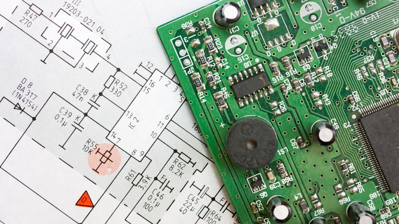
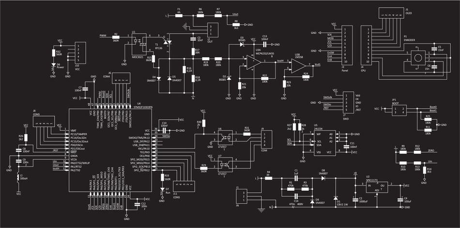
Schematic Drawing - Design of Electronic Circuit Board
Introduction
Schematics are the universal language of engineering, serving as detailed visual representations of complex systems and components. These intricate diagrams form the backbone of design, manufacturing, and troubleshooting processes across numerous industries, from electronics to aerospace. What are schematics? Curious about their significance?
Schematics offer a standardized way to communicate design intent, facilitate troubleshooting, and enable collaboration among engineers. Proficiency in reading and creating schematics is not just a valuable skill—it's an essential competency that enables effective communication, problem-solving, and innovation. In this technical article, we will explore what are schematics, their purpose, diverse types, critical applications and how to read and interpret them effectively.
Decoding the Schematic DNA: Essential Elements
Symbols: The Alphabet of Engineering
Schematic symbols form the foundation of engineering diagrams, providing a standardized visual language that goes beyond verbal and written communication barriers. These symbols represent specific components, connections, and functions within a system, allowing engineers to convey complex ideas efficiently and accurately.
In the world of schematics, symbols vary across different engineering disciplines, yet many share common traits or follow similar conventions. Key symbol categories in engineering schematics include:
Electrical and Electronic
Mechanical
Fluid Power (Hydraulic and Pneumatic)
Logic and Digital
Process Control
Architectural and Structural
Chemical and Process Engineering
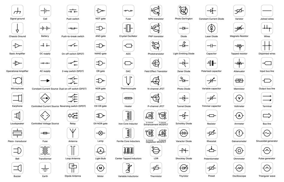
Electrical symbols represent the various components found in electrical circuits. Each symbol is standardized, allowing engineers from around the world to understand the design without ambiguity. Here's a table showcasing different electrical schematic symbols:
For engineers, technicians, and designers, being fluent in the “alphabet” of symbols is vital. It’s the foundation for designing systems that work seamlessly and for diagnosing issues when they don’t. The standardization of schematic symbols is crucial for several reasons:
Universal Understanding: Standardized symbols ensure that engineers worldwide can interpret schematics accurately, regardless of language barriers.
Efficiency: Familiar symbols speed up the design and review processes, reducing errors and miscommunication.
Interoperability: Standardization allows for seamless integration of components from different manufacturers or systems.
Education and Training: Consistent symbology simplifies the learning process for new engineers and technicians.
By mastering these symbol categories, engineers gain the ability to "read" schematics fluently. This enables them to quickly understand, design, and troubleshoot complex systems across various engineering disciplines.
Connections: The Grammar of Design
In schematic design, connections represent the paths along which signals, power, or mechanical forces travel. [1] These paths are as vital as the components themselves, as they define how energy and information flow through the system. The line types in schematics carry specific meanings:
Solid Lines: Typically represent primary connections or direct physical links between components. They are the most common type of line in schematics and often indicate the main signal or power flow paths.
Dashed Lines: Often used to show secondary or auxiliary connections. They may represent control signals, feedback loops, or alternative paths that are not always active.
Dotted Lines: Generally indicate weak connections, conceptual links, or potential future connections. In some cases, they may represent wireless or non-physical connections.

Connection representations go beyond simple lines. Junctions, where multiple lines meet, are often depicted as dots or small circles. These junctions can indicate whether lines are connected or merely crossing. Arrowheads on lines are frequently used to show the direction of signal or process flow, which is crucial for understanding the system's operation.
Signal flow concepts are fundamental to interpreting schematics correctly. They describe how information, energy, or materials move through a system. In electrical schematics, for instance, signal flow typically moves from inputs on the left to outputs on the right, while power connections are often shown vertically.
To effectively trace a signal or process flow in a schematic:
Identify the starting point (input) and endpoint (output) of the flow you want to trace.
Follow the lines connecting these points, noting any components or junctions along the way.
Pay attention to arrowheads or other directional indicators that show the flow's direction.
At each junction or component, determine how the signal is being modified or redirected.
Note any feedback loops or branching paths that might affect the main flow.
Consider the function of each component in the path and how it might alter the signal.
Verify that the traced path makes logical sense within the context of the overall system.
The common connection interpretation mistakes include:
Overlooking Line Type Differences: Failing to distinguish between solid, dashed, and dotted lines can lead to misunderstanding the system's structure.
Ignoring Junction Representations: Mistaking a crossing for a connection (or vice versa) can result in incorrect circuit analysis.
Misinterpreting Signal Flow Direction: Assuming all flows move in the same direction can lead to fundamental errors in understanding system operation.
Neglecting Feedback Loops: Overlooking these critical elements can result in an incomplete understanding of system behavior, especially in control systems.
Forgetting to Consider Component Functions: Tracing connections without considering how components modify signals can lead to incorrect predictions of system behavior.
By mastering the interpretation of connections and signal flows, engineers can effectively "read" schematics. This skill is crucial for design, troubleshooting, and optimization across all engineering disciplines.
Recommended Reading: PCB Layout: A Comprehensive Guide
The Schematic Spectrum: Types and Applications
Electrical Blueprints
Electrical schematics serve as the foundational language for designing, analyzing, and troubleshooting electrical and electronic systems. These visual representations provide a standardized method for communicating complex circuit designs and electrical connections. Two primary types of electrical schematics are:
Circuit diagrams, also known as schematic diagrams, focus on the functional relationships between components. They use abstract symbols to represent electrical elements and show how they interconnect to form a complete circuit. Circuit diagrams are essential for understanding the theoretical operation of a system and are widely used in design, analysis, and education.
Wiring diagrams, on the other hand, provide a more physical representation of electrical connections. They often use simplified component symbols or pictorial representations and show the actual layout of wires and connections. Wiring diagrams are crucial for the installation, maintenance, and troubleshooting of electrical systems in real-world applications.
Common electrical schematic components include:
Resistors: Represented by a zigzag line or rectangle
Capacitors: Shown as two parallel lines
Inductors: Depicted as a series of loops or coils
Diodes: Illustrated as a triangle pointing to a line
Transistors: Represented by various symbols depending on the type (e.g., BJT, FET)
Switches: Shown as a break in a line with various symbols for different types
Power Sources: Depicted as circles with positive and negative signs or battery symbols
Let's understand the common way of interpreting voltage, current, and resistance notations in electrical circuits.
Voltage is typically denoted by 'V' or 'E' and is measured in volts (V). In schematics, voltage sources are often labelled with their value, such as "12V" for a 12-volt supply. Voltage drops across components may be indicated by polarity symbols (+ and -) or by arrow notation.
Current is represented by 'I' and measured in amperes (A). Current flow is often shown using arrows along the connecting lines. In some cases, specific current values may be noted next to components or branches.
Resistance is symbolized by 'R' and measured in ohms (Ω). Resistor values are usually written next to the resistor symbol, often using metric prefixes (e.g., 1kΩ for 1000 ohms) or the standard resistor colour code.
Here’s a simple electrical circuit schematic:
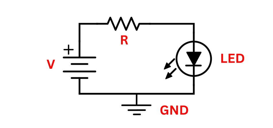
This schematic shows a basic LED circuit with a power source (V), a current-limiting resistor (R), an LED, and a ground connection (GND).
Electrical blueprints are a vital part of the schematic spectrum, forming the backbone of modern technology and infrastructure. Whether you're designing a new system or maintaining an existing one, understanding the different types and applications of electrical schematics is essential.
Mechanical Masterplans
Mechanical schematics serve as the visual language for designing, manufacturing, and maintaining mechanical systems. These detailed representations capture the intricate relationships between components, their spatial arrangements, and functional interactions. Unlike electrical schematics, mechanical diagrams often need to convey three-dimensional information on a two-dimensional plane, leading to unique representational techniques.
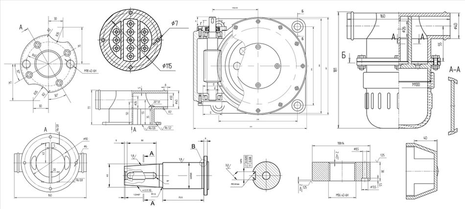
Assembly views are a crucial aspect of mechanical schematics. [2] These diagrams show how different components fit together to form a complete system or subsystem. Assembly views typically use a combination of lines, symbols, and annotations to indicate the relative positions of parts, their connections, and any specific assembly instructions. They are particularly useful for manufacturing processes and maintenance procedures, providing a clear roadmap for putting together or disassembling complex mechanical systems.
Exploded views take assembly diagrams a step further by visually separating the components while maintaining their spatial relationships. In an exploded view, parts are shown slightly apart from each other, often with dashed lines or arrows indicating their assembly paths. This technique allows for a clear visualization of each component's shape, orientation, and position within the overall assembly. Exploded views are particularly useful for illustrating complex assemblies, creating parts catalogs, and guiding assembly or disassembly processes.
Representing moving parts and mechanisms in mechanical schematics requires specialized techniques. Engineers often use a combination of static and dynamic representations to convey motion:
Kinematic Diagrams: These simplified schematics focus on the motion of parts, using lines and symbols to represent linkages, joints, and pivot points.
Motion Arrows: Curved or straight arrows indicate the direction and sometimes the magnitude of movement for specific components.
Multiple Position Overlays: Several positions of a moving part may be shown on the same diagram, often using different line styles or colors to differentiate positions.
Gear Tooth Representations: Specialized symbols and notations are used to accurately depict gear interactions and ratios.
Cam Profiles: The shapes of cams are carefully drawn to show how they interact with followers and create specific motion patterns.
2D and 3D mechanical schematics each have their strengths and applications. Here's a concise comparison:
| Aspect | 2D Schematics | 3D Schematics |
| Complexity | Simpler to Create and Read | More Complex, Requires Specialized Software |
| Detail Level | Limited Depth Perception | High Level of Detail, True Spatial Relationships |
| Production Cost | Lower, Faster to Produce | Higher, more Time Consuming |
| Modification Ease | Easier to Modify Quickly | More involved Modification Process |
| Software Requirements | Basic CAD or Drawing Software | Basic CAD or Drawing Software |
| Clarity of Assembly | May Require Multiple Views | Single View can show the Entire Assembly |
| Training Required | Less Training to Interpret | More Training for Full Comprehension |
| File Size | Smaller File Sizes | Larger File Sizes, more Resource Intensive |
| Manufacturing Use | Widely used in Traditional Manufacturing | Essential for Modern CNC and 3D Printing |
Both 2D and 3D schematics play crucial roles in mechanical engineering. The choice between them often depends on the specific application, available resources, and the complexity of the system being represented.
Software and Logic Roadmaps
Software and logic schematics play a crucial role in visualizing the structure, behavior, and logic of software systems and digital circuits. These visual representations help engineers and developers design, analyze, and communicate complex software architectures and logical operations.
Flowcharts are one of the most fundamental types of software schematics. They use standardized symbols connected by arrows to represent the sequence of operations in a process or algorithm. Flowcharts are particularly useful for illustrating the logic flow of programs, making them invaluable tools for both planning and debugging software.

Unified Modeling Language (UML) diagrams provide a more comprehensive set of tools for visualizing software systems. [3] UML encompasses various diagram types, each serving a specific purpose:
Class Diagrams: Represent the static structure of a system, showing classes, their attributes, methods, and relationships.
Sequence Diagrams: Illustrate the interactions between objects over time, highlighting the order of method calls and message passing.
Use Case Diagrams: Depict the functionality of a system from the user's perspective, showing actors and their interactions with the system.
Activity Diagrams: Similar to flowcharts but with additional features to represent parallel processes and decision points in complex workflows.
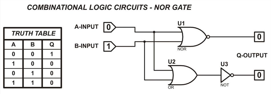
In digital logic schematics, logic gates are the fundamental building blocks. These gates perform basic logical operations on binary inputs to produce binary outputs. Common logic gates include:
AND Gate: Output is 1 only if all inputs are 1
OR Gate: Output is 1 if at least one input is 1
NOT Gate: Inverts the input (0 becomes 1, and 1 becomes 0)
NAND Gate: Combination of AND and NOT
NOR Gate: Combination of OR and NOT
XOR Gate: Output is 1 if inputs are different
Truth tables complement logic gate schematics by providing a tabular representation of all possible input combinations and their corresponding outputs. These tables are essential for understanding and verifying the behavior of logic circuits, especially as they become more complex.
Key elements of software schematics include:
Nodes or shapes representing processes, decisions, or data
Connectors or arrows showing the flow of control or data
Labels and annotations providing additional information
Swimlanes in activity diagrams to show responsibility or partitioning
Packages in UML to group related elements
Interfaces and inheritance relationships in class diagrams
Actors and system boundaries in use case diagrams
Lifelines and activation bars in sequence diagrams
Tip for using software tools for schematic creation:
When selecting a software tool for creating schematics, consider its compatibility with industry standards (like UML) and its ability to export to various formats.
Tools like Lucidchart, Draw.io, or Microsoft Visio offer extensive libraries of pre-built shapes, configurations and connectors, making it easier to create professional-looking diagrams.
For more specialized needs, consider using integrated development environments (IDEs) that offer built-in diagramming tools tailored for software architecture and design.
Software and logic roadmaps are more than just visualizations; they are a powerful language for planning, building, and maintaining robust software systems.
Recommended Reading: How to Design a PCB Layout: A Comprehensive Guide
Crafting Clarity: The Art of Schematic Design
Design Principles: The Foundation of Effective Schematics
The creation of effective schematics compromises three fundamental principles: clarity, consistency, and completeness. Clarity ensures that the schematic is easily understandable, with well-defined symbols and a logical layout. Consistency maintains uniform representation throughout the schematic, using standardized symbols and notation. Completeness guarantees that all necessary information is included, leaving no room for ambiguity or misinterpretation.
To achieve clarity, designers must prioritize readability by using appropriate spacing, avoiding clutter, and employing clear, legible labels. Consistency is maintained through adherence to industry standards and internal conventions i.e., ANSI, ensuring that similar components are represented identically throughout the schematic. Completeness is achieved by including all relevant components, connections, and annotations, providing a comprehensive representation of the system.
Steps for creating a schematic from scratch:
Define the scope and purpose of the schematic
Gather all necessary information about the system or circuit
Choose the appropriate schematic type (e.g., block diagram, circuit diagram)
Select a suitable drawing tool or software
Create a rough sketch or outline of the main components
Place the primary components on the drawing canvas
Add connections between components
Include secondary components and details
Label all components, connections, and values
Add annotations and notes for clarity
Review and verify the schematic for accuracy and completeness
Seek peer review or expert feedback
Make necessary revisions based on feedback
Finalize the schematic and prepare for documentation
Documentation and revision control play crucial roles in the schematic design process. Proper documentation ensures that the schematic can be understood and used by others, now and in the future. It includes detailed explanations of component choices, design rationale, and any assumptions made during the design process. Revision control, on the other hand, tracks changes over time, allowing designers to revert to previous versions if needed and maintain a clear history of the design's evolution. This is particularly important in collaborative environments or when working on complex, long-term projects.
For intricate schematics, consider these advanced techniques:
Hierarchical Design: Break down complex systems into manageable subsystems, using block diagrams to show high-level relationships and detailed schematics for each subsystem.
Color Coding: Utilize colors strategically to differentiate between various subsystems, voltage levels, or signal types. Ensure color choices are colorblind-friendly and maintain sufficient contrast.
Interactive Schematics: Implement hyperlinks or tooltips in digital schematics to provide additional information on components or subsystems without cluttering the main diagram.
Parametric Components: Use software that supports parametric components, allowing for easy updates of component values across the entire schematic.
Version Comparison: Employ tools that enable side-by-side comparison of different schematic versions to quickly identify and understand changes.
By following these principles and utilizing advanced techniques, engineers can create schematics that effectively communicate complex designs while maintaining clarity and accuracy.
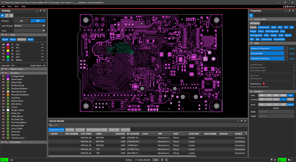
Digital Drafting: Mastering Schematic Software
The advent of digital tools has revolutionized the creation and management of schematics across various engineering disciplines. Modern schematic software offers powerful features that enhance precision, efficiency, and collaboration in the design process.
Several popular schematic software tools cater to different engineering fields and user needs:
AutoCAD Electrical: Widely used for electrical design, automation, and control systems.
Eagle: Popular among hobbyists and small businesses for PCB design and layout.
KiCAD: An open-source option favored by hobbyists and educational institutions.
Altium Designer: A professional-grade tool for high-end PCB design and simulation.
OrCAD: An industry standard for circuit simulation and PCB design.
Here's a comparison of these software options:
| Software | Features | Use Cases |
| AutoCAD Electrical | Comprehensive Toolset for Electrical Design, Automation, and Reporting | Electrical Schematics, Control Systems |
| Eagle | User-Friendly Interface, good for PCB Design and Layout | Personal Projects, Small Businesses |
| KiCAD | Open Source, capable of Schematic and PCB Layout | Hobbyists, Educational Use |
| Altium Designer | High-End Features for Professional PCB Design with Simulation | Professional Engineering Firms |
| OrCAD | Robust for Circuit Simulation and PCB Design | Industry Standard for Professionals |
Computer-aided design (CAD) offers several advantages over traditional drafting methods:
Precision: CAD tools allow for exact measurements and placement of components.
Efficiency: Repetitive tasks can be automated, saving time and reducing errors.
Collaboration: Digital files can be easily shared and worked on by multiple team members.
Version Control: Changes can be tracked and reverted if necessary.
Integration: Schematic designs can be directly linked to other stages of the design process, such as simulation or manufacturing.
Libraries: Extensive component libraries speed up the design process and ensure consistency.
Visualization: 3D rendering capabilities help in understanding complex designs.
This feature allows for quick access to standardized symbols, ensuring consistency and speeding up the schematic creation process. Most professional schematic software includes similar libraries, though the exact steps may vary.
Recommended Reading: PCB Design: A Comprehensive Guide to Printed Circuit Board Design
Reading Between the Lines: Schematic Interpretation
Cracking the Code: A Systematic Approach
Effective schematic interpretation is a crucial skill for engineers and technicians across various disciplines. By following a systematic approach, professionals can accurately understand and analyze complex systems represented in schematic form. Here's a comprehensive step-by-step guide to interpreting schematics:
Familiarize Yourself with the Schematic: Begin by reviewing the entire schematic to grasp its overall layout and identify major components. This initial overview provides context for the detailed analysis to follow.
Identify Symbols: Utilize a reference guide to recognize and understand the meaning of each symbol in the schematic. This step is crucial for accurate interpretation, especially when dealing with unfamiliar or industry-specific symbols.
Determine Input and Output: Locate power sources and outputs to understand the flow of energy or signals through the system. This step helps in visualizing the schematic's overall purpose and function.
Trace Connections: Carefully follow the lines connecting components, noting any junctions and types of connections. Pay attention to line styles (solid, dashed, or dotted) as they may convey different types of connections or relationships.
Understand Component Functions: Review the function of each component to comprehend its role within the system. This step is essential for understanding how the individual parts contribute to the overall functionality.
Check for Documentation: Look for accompanying notes, legends, or documentation that may provide additional context or instructions. These supplementary materials can offer valuable insights into design intentions or specific operational details.
Practice Review: Regularly interpret various schematics to build fluency and confidence in understanding complex designs. This ongoing practice is key to developing expertise in schematic interpretation.
Common pitfalls in schematic analysis and strategies to avoid them:
Misinterpreting Symbols: Always double-check unfamiliar symbols against a reliable reference guide. Avoid making assumptions based on similar-looking symbols.
Overlooking Connection Types: Pay close attention to different line styles and junction representations. Use a magnifying tool if necessary to distinguish between crossing and connecting lines.
Ignoring Context: Consider the broader context of the schematic, including its purpose and industry. Avoid interpreting components in isolation without considering their role in the larger system.
Neglecting Scale and Proportions: Be aware that schematic representations may not be to scale. Avoid making assumptions about physical size or layout based solely on the schematic.
Rushing the Analysis: Take the time to thoroughly examine each part of the schematic. Rushing can lead to missed details or misinterpretations.
Failing to Verify Understanding: If possible, cross-reference your interpretation with colleagues or additional documentation to ensure accuracy.
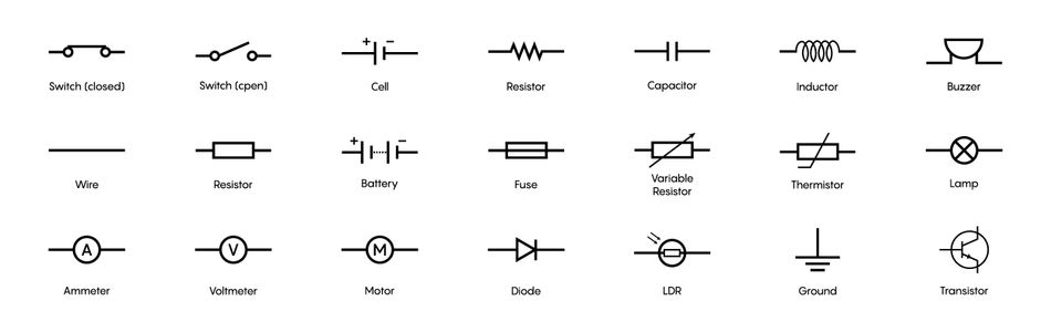
This quick reference guide provides a snapshot of common symbols encountered in electrical and electronic schematics. Always refer to industry-specific guides for more comprehensive symbol libraries.
Advanced Analysis: Beyond the Basics
Advanced schematic analysis techniques enable engineers to delve deeper into system behavior, optimize performance, and troubleshoot complex issues. These methods go beyond basic interpretation, leveraging sophisticated tools and approaches to extract maximum value from schematic representations.
Signal tracing is a fundamental technique in advanced analysis, allowing engineers to follow the path of a signal through a system. [4] This process involves identifying the signal source, tracking its progression through various components, and observing how it changes along the way. Signal tracing is particularly useful in debugging complex circuits, as it helps isolate issues to specific components or sections of the system.
Fault finding builds upon signal tracing, focusing on identifying and locating malfunctions within a system. This process often involves comparing expected behavior (as depicted in the schematic) with actual system performance. The advanced fault-finding techniques may include:
Nodal Analysis: Examining voltage levels at key points in the circuit
Loop Analysis: Investigating current flow through specific paths
Frequency Response Analysis: Assessing system behavior across different frequencies
System optimization leverages schematic analysis to improve overall performance. This may involve:
Component Value Adjustment: Fine-tuning resistor, capacitor, or inductor values
Topology Modifications: Rearranging circuit elements for better efficiency
Power Distribution Optimization: Ensuring proper voltage and current levels throughout the system
The integration of schematics with simulation tools has revolutionized performance analysis. Modern software allows engineers to create digital twins of physical systems, enabling:
Predictive Analysis: Forecasting system behavior under various conditions
Parameter Sweeping: Automatically testing a range of component values
Worst Case Scenario Testing: Evaluating system performance at extreme operating points
Thermal Analysis: Assessing heat distribution and identifying potential hotspots
These simulation capabilities provide valuable insights before physical prototyping, saving time and resources in the development process. Users can enhance schematic readability and analysis efficiency by utilizing color coding and layering:
Assign distinct colors to different voltage levels or signal types
Use layers to separate power distribution, signal paths, and control logic
Create a toggle-able layer for test points or debugging information
Implement a consistent color scheme across projects for easier interpretation
By leveraging these visual organization techniques, engineers can quickly identify relevant information and streamline the analysis process, especially in large and complex schematics.
Recommended Reading: How to Read a Circuit Board: Mastering the Language of Electronics
Conclusion
Schematics, the cornerstone of engineering communication, have evolved alongside technology. While their core principles remain unchanged, digital tools have enhanced their precision and capabilities. The ability to create, interpret, and analyze schematics is a fundamental skill for engineers, enabling efficient design, troubleshooting, and innovation. As technology continues to evolve, the future of schematics holds exciting possibilities, potentially incorporating augmented reality or AI-assisted design. By embracing these advancements, engineers can ensure that schematics remain a vital tool for shaping the innovations of tomorrow.
Frequently Asked Questions
Q: What is the primary purpose of a schematic?
A: The primary purpose of a schematic is to provide a clear, standardized visual representation of the components of a system and their interconnections. This facilitates design, analysis, and communication among engineers.
Q: How do electrical schematics differ from mechanical schematics?
A: Electrical schematics focus on representing electronic components and their connections, often using abstract symbols. Mechanical schematics typically depict physical components and their spatial relationships, often incorporating more realistic representations or multiple views.
Q: What are some common mistakes to avoid when creating schematics?
A: Common mistakes include using non-standard symbols, overcrowding the diagram, and neglecting to label components or values. Failing to maintain consistent orientation and scale throughout the schematic are a few more mistakes.
Q: What legal considerations should be kept in mind when working with schematics?
A: Schematics can be subject to intellectual property rights. When creating or using schematics, consider copyright laws, patent implications, and any non-disclosure agreements. Always obtain proper permissions when using or modifying schematics created by others, especially in commercial applications.
Q: How are schematics evolving with advancements in technology?
A: Modern schematics are increasingly digital, interactive, and three-dimensional. Advancements include integration with CAD/CAM systems, incorporation of augmented reality for visualization, and the use of AI for automated design and optimization.
References
[1] MKTPCB. A Comprehensive Guide to Schematic Diagram [Cited 2024 October 29] Available at: Link
[2] AZILL. What Are Assembly Drawings? Different Types Explained! [Cited 2024 October 29] Available at: Link
[3] Visual Paradigm. What is Unified Modeling Language (UML)? [Cited 2024 October 29] Available at: Link
[4] Altium. Understanding Connectivity on Your PCB [Cited 2024 October 29] Available at: Link
Table of Contents
IntroductionDecoding the Schematic DNA: Essential ElementsSymbols: The Alphabet of EngineeringConnections: The Grammar of DesignThe Schematic Spectrum: Types and ApplicationsElectrical BlueprintsMechanical MasterplansSoftware and Logic RoadmapsCrafting Clarity: The Art of Schematic DesignDesign Principles: The Foundation of Effective SchematicsDigital Drafting: Mastering Schematic SoftwareReading Between the Lines: Schematic InterpretationCracking the Code: A Systematic ApproachAdvanced Analysis: Beyond the BasicsConclusionFrequently Asked QuestionsReferences