Countersinks in PCB Design: Definition, Applications & Best Practices
A countersink in PCB design is a conical recess that allows flat-head screws to sit flush with the board surface. This article explores countersinks vs. counterbores, when to use them, IPC standards, manufacturing considerations, and best practices to ensure reliable, cost-effective PCB designs.

28 Mar, 2025. 31 minutes read
No time now? Save for later.
We only use your email to send this link. Privacy Policy.
Introduction
Ever tried sinking a screw into a piece of fine woodworking and realized the shank needed a conical hole for a flush fit? The same principle applies to PCB design. When fastening a PCB to a workpiece—be it an enclosure, sheet metal, or another board—standard screw heads can stick out, causing clearance issues. That’s where countersink holes come in. Much like how a pilot hole guides a screw into wood, a countersink in a PCB allows flat-head screws or even a rivet to sit seamlessly within the board, preventing interference and improving both aesthetics and mechanical stability.
In PCB design, mechanical precision is as critical as the electrical layout. A well-placed countersunk hole ensures a secure fit while maintaining a sleek, compact profile—key for space-constrained applications like wearables and high-end electronics. However, incorporating countersinks requires careful manufacturing planning, as improper specifications can lead to a weakened board structure or increased production costs.
Countersinking in PCBs differs from other mechanical hole modifications like counterbores or simple chamfers. While counterbores create flat-bottomed recesses for non-tapered fasteners, countersinks are designed explicitly for screws with a tapered head. Proper implementation involves defining parameters such as hole depth, angle, and plating requirements in manufacturing files. Adherence to industry standards like IPC-2221 ensures that countersunk holes maintain structural integrity without compromising the board’s functionality.
Recommended reading: PCB Design: A Comprehensive Guide to Printed Circuit Board Design - Part 1
What Is a Countersink?
In PCB design, a countersink is a conical recess at the top of a drilled hole, allowing the head of the screw to sit flush or slightly below the board's surface. This prevents interference with other components, ensuring a smooth, professional finish. Countersinking is widely used not only in electronics but also in woodworking and sheet metal fabrication, where flush-mounted fasteners improve both aesthetics and functionality.
Countersinks are often compared to counterbores and chamfers, which serve different purposes. A counterbore creates a flat-bottomed cylindrical recess, ideal for screws or bolts with non-tapered heads, such as socket-head cap screws. A chamfer, on the other hand, is a shallow bevel applied to an edge or hole, mainly for deburring or guiding fasteners into place.
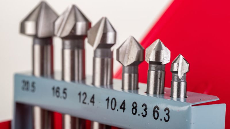
To create a countersink in a PCB, manufacturers use a fluted countersink bit—often made from carbide for durability. This tool enlarges the top of a pilot hole, forming the necessary angled profile for a flat-head screw. The process typically follows the initial drilling step and may involve deburring to remove sharp edges. Proper use of clamps during machining ensures the workpiece remains stable, maintaining precision in the final product.
Types of Countersink
Countersinking is essential in various applications, from PCB design to woodworking and metalworking, ensuring a smooth surface by allowing screws to sit flush with the material. Different types of countersinks are available, each designed for specific materials, screw types, and applications.
1. Standard Countersink
A standard countersink is the most common type, designed specifically for flat-head screws. It features a conical cut that matches the taper of the screw, allowing it to sit flush with or slightly below the surface. This type is widely used in PCBs, furniture assembly, and sheet metal fabrication, where a screw flush finish prevents snags and maintains a sleek appearance. In electronic enclosures, standard countersinks prevent screws from protruding, avoiding interference with other components inside the casing.
2. Fluted Countersink
A fluted countersink has specially designed cutting grooves that enhance chip removal during drilling. These flutes help prevent material buildup, reducing friction and ensuring a clean, precise cut. This type is especially useful when working with softer materials like plastic, wood, and aluminum, where excess material might otherwise clog the hole. In woodworking, a fluted countersink prevents tear-out when installing screws into delicate wood surfaces, ensuring a smooth surface finish. Similarly, plastic enclosures help avoid melting due to excessive heat from friction.
3. Adjustable Countersink
An adjustable countersink allows depth control, making it suitable for various screw sizes and applications. The cutting depth can be fine-tuned, ensuring that the head of the screw sits precisely where needed. This versatility makes it a preferred choice for precision machining and custom fabrication work. In aerospace applications, adjustable countersinks help maintain strict tolerances when securing panels with tapered screws, ensuring each fastener sits at an exact depth for aerodynamic efficiency.
Distinguishing Countersink from Counterbore and Chamfer
In precision manufacturing, understanding the differences between countersink, counterbore, and chamfer is crucial for selecting the right hole modification technique. Each serves a specific function, depending on the fastener type, material, and structural requirements.
Counterbore: Flat-Bottomed Recess for Non-Tapered Screws
A counterbore is a cylindrical, flat-bottomed recess drilled into a material, creating a wider cavity at the top of a hole. Unlike a countersink, which has an angled profile, a counterbore has straight vertical walls and a flat bottom, allowing for the insertion of non-tapered screw heads such as pan-head, hex-head, or socket-head screws.
Functionality: The primary purpose of a counterbore is to allow larger screw heads to sit flush or below the surface of the workpiece, preventing interference with moving parts or ensuring a smooth assembly. Unlike countersinks, counterbored holes are often deep enough to accommodate washers for increased load distribution.
Example:
In machinery assembly, counterbored holes are used to recess cap screws, ensuring they do not protrude and interfere with adjacent components.
In PCBs, counterbores can be used for mounting standoffs or fastening enclosures, where screws with cylindrical heads need to sit below the board’s surface.
Manufacturing Process:
A counterboring tool with a pilot bit is used to create the initial drilled hole, followed by a larger cylindrical cutter to expand the recess.
Materials such as aluminum, steel, and even PCB laminates require different counterbore depths depending on the application.
Key Difference: A counterbore is ideal for non-tapered screws and provides a flat-bottomed recess, whereas a countersink is angled for tapered screws.
Recommended reading: Counterbore vs Countersink: Key Differences and When to Use Each
Chamfer: Beveled Edge for Smoother Transitions
A chamfer is a beveled edge applied to the top of a hole or the outer edges of a material. In contrast to both countersinking and counterboring, chamfering does not create a seating surface for a screw head but instead removes sharp edges for better fit and reduced material stress.
Functionality:
Chamfers guide screws into holes more easily, improving assembly precision.
They eliminate burrs and sharp edges, which can cause misalignment or material failure.
In PCB design, edge chamfering is commonly applied to connector edges, making insertion smoother.
Example:
In sheet metal work, chamfering is used to reduce stress concentrations, preventing cracks.
In woodworking, chamfers are used for decorative finishes and to facilitate better joint fitting.
In machining, chamfers help lead bolts into holes and prevent thread damage.
Manufacturing Process:
Chamfers can be created using a chamfer bit, a lathe, or grinding tools for fine adjustments.
The angle of a chamfer can vary but is usually 15° to 45°, whereas a countersink is typically 60° to 90° to match flat-head screws.
Key Difference: A chamfer is not a recess for screws but a beveled edge, whereas a countersink is an angled cut specifically for tapered fasteners.
Recommended reading: How Fillets and Chamfers Impact CNC Machining Costs
When to Use Each
Feature | Countersink | Counterbore | Chamfer |
Shape | Conical | Cylindrical | Beveled Edge |
Fastener Type | Tapered (Flat-Head Screws) | Non-Tapered (Pan, Hex, Socket Screws) | No fastener seating |
Purpose | Allows screws to sit flush or below the surface | Recesses large screw heads for flush mounting | Smooths edges, prevents burrs, aids insertion |
Common Angle | 60°, 82°, 90° | 90° (Flat-Bottomed) | 15° to 45° |
Used In | PCBs, woodworking, metalworking | Machinery, structural assembly | Sheet metal, machining, decorative edges |
Example | Fastening PCB standoffs | Mounting bolts in machine housings | Reducing stress on sharp edges |
In practice, both countersinks and counterbores are used to flush-mount screws in a PCB, but the choice depends on the type of screw. If your design uses standard flat-head screws (with tapered undersides), you’d specify a countersink. If it uses a bolt or screw with a flat bottom under the head (like a hex socket cap screw) or needs a washer, you’d use a counterbore. Chamfering is more of a minor feature used for finishing rather than securing hardware.
Why Are Countersinks Used in PCB Design?
Countersinks play a critical role in PCB design by allowing fasteners to sit flush or slightly below the surface of the board. This specialized feature brings several mechanical, functional, and design-related advantages, especially in applications where precision, space management, and safety are paramount. Here are the key reasons why countersinks are an essential tool in modern PCB design:
1. Mechanical Stability and Safety
One of the primary purposes of countersinking in PCB design is to secure screw heads flush with the board’s surface, which prevents the protrusion of fasteners. This design choice enhances the mechanical stability of the assembly and contributes to the safety of electronic devices.
Prevents Snagging and Misalignment: When screws sit flush, there is no risk of the screw head interfering with other components or external parts. This is particularly vital in applications where precision and alignment are crucial. For instance, in aerospace or automotive electronics, where vibration or shock forces are common, countersunk screws help keep the assembly tight and secure, preventing screws from loosening over time.
Enhanced Load Distribution: A flush screw distributes its load more evenly across the PCB, improving the overall fastening strength. This is especially beneficial when securing components in systems with high-frequency vibrations, where electromagnetic interference (EMI) might also be a concern. The flush screw head also minimizes the risk of short circuits, as it ensures the screw does not come into contact with other conductive surfaces.
Example:
In automotive electronics (e.g., control modules or sensors), countersunk screws secure PCBs to metal brackets without the risk of the screw heads catching on other components during high-speed movements or vibration, thus improving both safety and durability.
2. Space Savings in Compact Designs
As electronic devices become more compact, optimizing space within the assembly becomes critical. Countersinks play a crucial role in allowing fasteners to be recessed into the board, saving vertical space.
Optimizing Compact Designs: In slim devices like smartphones or smartwatches, even the slightest protrusion can prevent proper fitment inside tight enclosures. By countersinking the screws, the heads remain below the board surface, enabling other components or PCBs to be placed on top or stacked without interference. This provides more space for other electronics or functional layers.
Example:
Smartphones require compact PCBs where countersunk screws ensure that the PCB can fit in a slim case, allowing for optimal component placement while maintaining a sleek exterior. Countersinking also allows the PCB to stack neatly in multi-layer assembly designs without any height clearance issues.
3. Improved Aesthetics and Product Feel
Countersunk screws not only have functional benefits but also contribute to the aesthetic quality of the final product. A smooth, flush surface provides a more professional and sleek appearance.
Enhanced Visual Appeal: When the screw heads are countersunk, they do not stick out of the board, ensuring a smooth finish. This is important in consumer electronics where the device’s exterior appearance matters. In open-frame devices, lab equipment, or wearables, countersunk screws contribute to a clean and refined look.
User Experience: In wearable technology (e.g., smart watches), users won’t feel a bump from the screw head because it is embedded within the board, making the product more comfortable to wear. This improves the overall perception of the device's quality.
Example:
In medical devices that require a professional finish, countersunk screws ensure that the exterior is free from protruding fasteners, which could otherwise detract from the product’s sterility or aesthetic appeal.
4. Aerodynamics and Clearances
For PCBs used in aerodynamic environments (e.g., in drones or automotive sensors), minimizing surface irregularities is crucial. Countersinks help maintain a smooth profile that does not disrupt airflow or cause unnecessary drag.
Preventing Airflow Disruption: When a PCB is mounted on a drone or within a vehicle, any protruding fastener could affect the aerodynamics, increasing resistance and compromising performance. By countersinking the screws, manufacturers ensure that the screw heads are not causing any turbulence, enabling optimal airflow.
Example:
In drones, where aerodynamics plays a significant role in battery life and flight stability, countersunk screws ensure that the PCB mounting is smooth and streamlined, preventing unnecessary air resistance during flight.
5. Mounting to Surfaces/Enclosures
Countersinks are essential when mounting a PCB to a surface or enclosing it within a chassis. In these cases, flat-head screws are often used to ensure that the PCB is tightly secured to prevent movement, all while maintaining a flush surface for easy integration.
Mounting with Flat-Head Screws: When mounting PCBs to metal panels or brackets, countersinking ensures that the screw heads are flush with the board’s surface, allowing for a secure and stable fit. This also prevents interference with other devices or PCBs stacked in the same enclosure.
Example:
When stacking multiple PCBs in server enclosures or electronics modules, a countersunk screw allows each PCB to be mounted securely, with the screw heads not interfering with the adjacent layers or standoffs.
Recommended reading: SMT Manufacturing: Everything You Need to Know
How Countersinks Are Implemented in PCB Manufacturing
Implementing countersinks in PCB manufacturing requires specialized processes, precision tooling, and careful attention to design specifications to ensure reliability and functionality. This multi-step procedure involves several important considerations, including the drilling process, adherence to industry standards, material considerations, and potential impact on the PCB’s mechanical strength. Below is a detailed breakdown of how countersink holes are created and the technical aspects involved:
1. Drilling Process
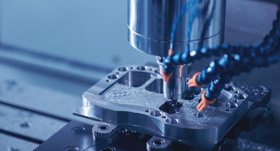
The creation of countersink holes in a PCB typically involves a two-step drilling process. The procedure begins with drilling the through-hole, which accommodates the body of the screw. This is followed by a countersink operation, where a larger conical bit is used to create a recessed, angled section at the top of the hole. The countersink bit has a conical cutting head that allows for precise shaping of the hole.
The process is conducted on a Computer Numerical Control (CNC) drilling machine, which ensures high precision. It is important to note that countersinking cannot usually be done while the boards are stacked together, as each hole must be drilled individually to maintain precise depth and angle. This one-at-a-time drilling process can lead to longer production times.
The location of the countersink—whether on the top, bottom, or both sides of the PCB—depends on the design requirements. For instance, if the screw must be seated flush from the top of the board, a countersink will be created on the top side. Conversely, for screws inserted from the bottom, the countersink will be performed on the underside of the PCB.
2. IPC Standards and Tolerances
Adhering to industry standards such as IPC-2221 is crucial for ensuring that the mechanical features of a PCB, including countersinks, are properly designed and manufactured. The IPC-2221 standard provides guidelines for hole tolerances, which apply to countersunk holes as well.
The depth and angle of the countersink must be controlled within tight tolerances to ensure that the screw fits correctly. For example, manufacturers commonly specify a tolerance of ±0.20 mm for depth and ±5° for the countersink angle. These values help ensure that screws sit properly, preventing issues like misalignment or inadequate seating.
The countersink angle is often standardized at 82° for ANSI screws, but variations (such as 90°) may be used depending on the screw type. Designers must specify the angle if it deviates from the standard to avoid compatibility issues with fasteners.
3. Material Considerations
The material used for the PCB laminate, such as FR-4 fiberglass, plays a significant role in the countersinking process. When countersinking, the drill bit cuts through both the copper plating and the laminate, which can sometimes result in rough edges if not executed carefully. Proper drill speed and feed rates must be controlled to prevent delamination or burning of the material.
If the board has copper plating at the countersink location, the copper in the conical recess will be partially removed. This is especially important in plated-through holes (PTH), where the copper plating along the hole walls is intended to form electrical connections. Since countersinking typically occurs after the plating process, this can leave exposed copper edges in the conical section, which may require additional finishing to maintain durability and avoid electrical issues.
To protect exposed material, fabricators may apply coatings or finishes to prevent oxidation and ensure the longevity of the PCB. When countersinking very thin boards, designers must ensure enough material remains below the countersink to avoid weakening the structure of the PCB. For example, countersinking on a thin 1 mm PCB might lead to over-cutting if not done cautiously, risking structural failure.
4. Impact on PCB Strength
Countersinking reduces the overall thickness of the PCB in the area around the hole, potentially compromising the mechanical integrity of the board. This is particularly true when the countersink is deep or placed too close to the edge of the board or adjacent holes. The conical shape of the countersink can act like a wedge, which, if over-tightened, could cause the laminate to crack or split around the hole.
To avoid such issues, careful control of countersink depth and angle is critical. The depth should be set so that the screw fits flush with the board, rather than being driven too deep, which could cause damage. Additionally, designers should observe appropriate clearance guidelines to ensure that countersinks do not weaken areas that are too close to edges or other holes. If necessary, additional support (such as washers) can be used to distribute the load, though flat-head screws typically do not require washers.
5. Plated vs Non-Plated Countersink Holes
In many cases, PCB mounting holes are non-plated through holes (NPTH), meaning the copper plating does not extend through the hole. Countersink holes can follow this same approach, but there are instances where plating may be necessary. For example, if the screw is intended to form an electrical connection (such as grounding the PCB to a chassis), plating is required to ensure that the screw can make contact with the copper.
Manufacturers must be informed in advance if a countersink hole needs to be plated. A typical approach is to plate the through-hole first and then perform the countersink drilling, which removes plating from the top surface while leaving the plating intact on the walls of the hole. However, if plating is not requested, the countersink hole may not achieve the expected electrical conductivity, especially in cases where the screw is intended to ground the PCB to an external metal part.
6. Equipment and Cost Considerations
Countersinking is not always a standard feature in PCB manufacturing, especially for prototype or small-scale production runs. This process often requires specialized tooling and additional setup time. In some cases, manual intervention or a separate CNC operation is necessary, increasing both production time and cost. Additionally, if countersinks are needed on both sides of the PCB (for screws inserted from either side), this doubles the number of operations required, further increasing costs.
Moreover, countersinking typically requires drilling individual boards, which can be less efficient than batch processing where boards are stacked. This is a key consideration for cost-sensitive projects, and designers should weigh the need for countersinks against the added complexity. Some manufacturers may even suggest alternative solutions (such as using alternative fastener designs) if they believe countersinking will unnecessarily complicate the project.
Design Considerations for Countersinks in PCB Layout
Designing a PCB with countersink holes requires more than just defining a hole in your CAD software. Because countersinks are mechanical features that affect both assembly and fabrication, proper documentation is crucial to ensure that manufacturers implement them correctly. Below are key considerations and best practices for specifying countersinks in PCB design files.
1. Specifying Countersinks in Design Files
Standard Gerber files, which define PCB artwork layers, do not fully capture countersink details since these are mechanical drilling features. Instead, you need to specify them using dedicated methods:
NC (Numerical Control) Drill Files
Some PCB CAD tools, such as Cadence Allegro and Altium Designer, allow you to generate separate NC (Numerical Control) drill files for countersinks. These files define the coordinates and parameters of countersink operations, distinct from regular plated and non-plated holes.
Cadence Allegro: Provides an option to generate a separate drill file specifically for countersinks, often named something like *-cd-TOP.drl for the top-side countersinks.
Altium Designer: Requires defining countersinks in the mechanical layer and exporting them as a dedicated drill file or including additional fabrication notes.
NC (Numerical Control) drill files provide exact coordinates and diameters of holes to be drilled in a PCB (Printed Circuit Board) or other materials. However, these files alone do not include information about:
Hole depth (how deep the hole should be drilled)
Drill angle (whether the hole is straight or at an angle)
To ensure proper manufacturing, additional notes must be provided to clarify these details, especially for complex designs requiring blind, buried, or angled holes.
Fabrication Drawings
In PCB manufacturing, countersink holes must be precisely defined in the fabrication drawing on the mechanical layer to ensure accurate production. These holes are typically represented using standardized symbols, such as a ⌵ or “V” shape, which visually depicts the cross-section of a countersink. A typical call-out might be formatted as “⌀3.0 mm through, ⌵ 6.0 mm x 90° from the top”, specifying a 3 mm through-hole with a 6 mm diameter, 90° countersink from the top side. For additional clarity, a detailed annotation such as “Countersink Ø5.5 mm x 90° on top side for flat head screw M3” explicitly defines the hole dimensions, taper angle, and intended screw type.
To prevent fabrication errors, the drawing must indicate:
Board Side – Whether the countersink is applied from the top or bottom layer.
Outer Diameter – The full diameter of the countersink (typically matching the screw head size).
Countersink Angle – Commonly 82° or 90°, depending on the flat-head screw standard being used.
Some PCB design standards may also specify tolerance requirements to ensure consistency across multiple production runs. Properly documenting these details in Gerber mechanical layers or dedicated drill files helps prevent misinterpretation by the fabricator, ensuring seamless assembly and compatibility with fasteners.
Separate Drill Instructions for Countersinks
If your PCB design software does not support dedicated countersink drill file generation, designers must provide clear instructions to ensure correct hole machining. A common workaround is to define the same hole with two different diameters in the NC drill file—one entry for the through-hole and another for the countersink diameter. This method ensures that the countersink operation appears in the drill report, making it distinguishable from standard drilled holes.
For example, the drill report may include:
Hole ID | Diameter (mm) | Drill Type |
H1 | 3.0 | Through-hole |
H1 | 6.0 | Countersink |
Since drill files alone do not inherently specify a countersink, additional documentation is essential. Designers should:
- Include a Fabrication Note – Explicitly state that the larger diameter corresponds to a countersink operation, including details such as countersink angle (e.g., 82° or 90°).
- Use Mechanical Layer Drawings – Supplement the drill data with a fabrication drawing that details the countersink parameters, including diameter, depth, and board side (top or bottom).
- Communicate with the Manufacturer – Since a modified drill file may be misinterpreted, direct communication with the PCB fabricator is recommended to confirm countersink requirements.
While this method offers flexibility, it is not self-explanatory and relies on clear, standardized documentation to prevent manufacturing errors.
2. Essential Information for Countersink Fabrication
To ensure accurate countersink hole fabrication, PCB manufacturers require precise details. Providing comprehensive specifications eliminates ambiguity and reduces manufacturing errors. The following key parameters should be included for each countersink hole:
Hole Location and Orientation – Clearly specify the position of the hole and indicate whether the countersink is on the top, bottom, or both sides of the PCB.
Through-Hole Diameter – Define the final size of the main hole, which should match the screw shaft diameter to ensure a proper fit.
Countersink Major Diameter – Specify the diameter of the opening at the board surface, typically slightly larger than the screw head diameter to allow clearance.
Countersink Angle – Provide the required countersink angle, commonly 82° or 90°, to match standard flat-head screws.
Countersink Depth – If a precise depth is necessary, specify it numerically to ensure the screw sits at the desired level. While depth can often be derived from the diameter and angle, explicitly stating it helps avoid misinterpretations. A safer approach is to define depth in terms of remaining board thickness.
Plated or Non-Plated Hole (PTH/NPTH) – Typically, mounting holes are non-plated (NPTH), but if plating is required (e.g., for grounding purposes), it must be clearly marked in the design file by defining the hole as plated and adding pads, or by specifying it in the fabrication drawing.
Tolerances – If specific tolerances are needed beyond standard manufacturing allowances, indicate them explicitly. Critical fits, such as for custom hardware, may require tighter tolerances on both diameter and angle.
Providing all this information removes ambiguity. Fabricators like to see a clear note like: “Holes A, B: Drill 3.00 mm ±0.05, countersink 6.00 mm ±0.1 to 90° on top side. Non-plated.” This way they don’t have to guess your intent.
Recommended reading: Through Hole vs Surface Mount: Unveiling the Optimal PCB Assembly Technique
3. PCB Layout Tool Constraints: Handling Countersinks Across Different CAD Tools
Different PCB CAD tools manage countersink features in distinct ways, so it’s important to understand their limitations and adjust accordingly to ensure accurate manufacturing.
Altium Designer: In Altium, you can define countersinks in the pad stack for mounting holes, specifying the top taper. However, by default, Altium does not automatically output countersink details in the Gerber or NC drill files. Instead, countersink information is typically included in the mechanical layer, which is then referenced through a drawing. In recent versions, Altium has made improvements, allowing users to include a mechanical layer pair specifically for counterbore or countersink details, improving the overall documentation.
KiCad: KiCad, as of now, lacks a dedicated countersink hole feature. The common workaround is to create a standard hole and then annotate it with a mechanical note, either directly on the board edge layer or via a separate DXF file. This annotation can indicate the countersink requirement. Users often place these mechanical details on the board-edge layer or use a dedicated mechanical drawing to ensure the countersink is clearly communicated to the manufacturer.
Cadence Allegro: Unlike Altium and KiCad, Allegro offers a specific countersink output option, making it a more streamlined choice for designers who need precise countersink information. The software allows users to designate countersunk holes and include them in the drill files, simplifying the communication process during manufacturing. This explicit feature is particularly helpful for teams using Allegro's workflow.
General Advice: Regardless of the CAD tool, always double-check your Gerber and drill outputs. Verify that countersink holes are accurately reflected in the drill files (for through-holes) and that the corresponding fab drawing maps to these holes. It’s also recommended to consult with your PCB manufacturer before finalizing the design. Some manufacturers may prefer an annotated PDF drawing to indicate countersinks, while others may request an additional NC drill file with countersink specifications. Communication with your PCB vendor is crucial to avoid any misunderstandings during the fabrication process.
4. Dimensions and Angles:
When designing PCB countersinks, use standard screw sizes and angles to ensure manufacturability. U.S. flat head machine screws typically require an 82° countersink (Unified Thread Standard), while metric flat head screws use 90°. IPC standards don’t mandate angles but recommend matching the screw, so always choose the fastener first and then specify the countersink accordingly. Common angles like 82° and 90° are widely supported by PCB manufacturers, but less common angles (e.g., 100° or 120°) may require special tooling. The countersink diameter should be slightly larger than the screw head diameter for a proper fit—e.g., a 6 mm screw head may require a 6.5 mm countersink to avoid wedging. PCB thickness is crucial; a 2 mm PCB cannot fully countersink a screw with a 3 mm under-head height without cutting through. In such cases, options include allowing a partially protruding head, using a thinner head screw, or opting for a counterbore instead. Always verify these details with your manufacturer to prevent fabrication issues.
5. Avoiding Common Mistakes:
To avoid common pitfalls when designing PCB countersinks, consider the following technical aspects:
Specify the countersink location: Always indicate whether the countersink is on the top, bottom, or both sides of the board. If unspecified, most PCB fabs assume the top layer, which may be incorrect for your assembly. For instance, if mounting a component that requires a flush screw from the bottom, but the countersink is fabricated on the top, it will render the design ineffective.
Match the countersink angle to the screw standard: Using a 90° countersink for an 82° flat-head screw (per Unified Screw Threads standard) results in improper seating, leading to stress points. For metric screws, 90° is common, but some applications may require 100° or 120°. Verify the screw’s specification first, then define the countersink accordingly. In KiCad, since there’s no built-in countersink feature, using a mechanical drawing annotation in the board-edge layer or an external DXF file helps communicate the correct angle.
Ensure proper clearance for copper and components: The countersink flaring at the top increases the effective hole diameter. A #4-40 flat head screw (~7.8 mm head diameter) in an 82° countersink could require an 8.5 mm top diameter. If copper traces or ground pours are placed within this zone, they could be removed during fabrication or cause electrical isolation issues. Similarly, components should not be placed within 1.5× the countersink diameter to avoid interference.
Properly define plating requirements: If the countersunk hole is intended for electrical connectivity, it must be explicitly marked as PTH (plated through-hole) in the PCB design tool. Some CAD tools, like Altium Designer, may require a mechanical layer definition for the countersink, while KiCad typically requires a manual note or DXF overlay. If an NPTH (non-plated through-hole) is mistakenly plated, it can result in shorts or unintended grounding issues. Conversely, if a plated hole is assumed to be NPTH, it could break a required connection, leading to functional failures.
Consult the PCB manufacturer on fabrication constraints: Different fabs have different minimum hole size-to-countersink ratios. For example, a 2.5 mm hole may require a minimum PCB thickness of 1.6 mm to accommodate an 82° countersink without excessive material removal. Some manufacturers limit countersink depths to 50% of the PCB thickness, while others require a minimum hole diameter of 3 mm before countersinking. Always verify these parameters before finalizing a design.
Prevent structural weaknesses in thin boards: If countersinking from both sides, ensure at least 0.5 mm of material remains at the thinnest section to avoid mechanical failure. For example, a 1.6 mm PCB with opposing 120° countersinks would leave almost no structural integrity. In such cases, either use a thinner flat-head screw or increase PCB thickness. Manufacturers typically caution against double-sided countersinks unless the board is ≥ 3.2 mm thick due to drill stability and material strength issues.
Verify documentation and outputs: Before fabrication, check the Gerber, NC drill, and assembly drawings to confirm that countersinks are correctly defined. Some manufacturers prefer a dedicated countersink drill file, while others accept annotated fabrication drawings in PDF format. Failing to clarify this can result in missing countersinks or incorrectly sized holes.
6. Additional Considerations
Material Constraints – Countersinking in FR4, aluminum-core (IMS), or composite PCBs requires precise tool speeds and feeds to prevent delamination, fiber tear-out, or excessive heat buildup. For metal-core PCBs (MCPCBs), countersinking can introduce burr formation or stress fractures if improper drilling techniques are used. Manufacturers typically use carbide or diamond-coated drill bits with optimized spindle speeds to maintain hole integrity.
Tolerance & Manufacturing Variability – Standard countersink depth tolerance is ±0.05 mm, with an angle tolerance of ±1° to ensure proper screw seating and avoid mechanical stress. In multilayer PCBs, countersinking may reduce the dielectric thickness between layers or expose inner copper planes, potentially causing short circuits or impedance shifts. Using simulation tools or stack-up analysis can help mitigate these risks before fabrication.
Alternative Fixing Methods – If the PCB thickness is insufficient for a full-depth countersink, typically in boards thinner than 1.6 mm, alternative mounting solutions can be used to ensure secure fastening without compromising structural integrity. Press-fit fasteners, such as PEM® inserts, provide a flush mounting surface without requiring a countersink, making them ideal for thin PCBs. Countersunk washers help distribute screw pressure evenly while maintaining a flat surface, reducing the risk of material deformation. Additionally, threaded inserts or standoffs can be bonded to the PCB, allowing for reliable screw retention without modifying the board structure.
Practical Applications & Case Studies
Countersink holes in PCBs are widely used across various industries, each with unique design constraints and best practices. Below are real-world applications illustrating how countersinks improve PCB functionality.
1. Consumer Electronics (Smartphones & Wearables)
Modern compact devices like smartphones and smartwatches rely on countersunk screws to optimize internal space. For instance, in a smartphone assembly, the main PCB is secured to the chassis using M1.6 flat-head screws, ensuring the screw heads sit flush. This prevents interference with other components such as batteries, displays, or connectors.
A case study on wearable device miniaturization highlighted how a 1.2 mm-thick smartwatch PCB incorporated 90° countersinks (3.2 mm diameter, 0.5 mm deep) to accommodate M1.6 screws with 3 mm heads. This design freed up additional vertical space, allowing for a thicker battery. The designers employed 3D CAD modeling to verify clearances and collaborated with the fabricator to confirm the feasibility of micro-countersinks on thin boards.
Best Practices:
Use the smallest possible screw size to reduce countersink depth.
Verify in 3D CAD models that the screw head remains flush without causing interference.
Engage the fabricator early to confirm countersink tolerances on thin PCBs.
2. Mechanically Stacked PCBs (Embedded Systems & Modular Hardware)
In modular hardware systems, multiple PCBs are stacked using standoffs and fasteners. When a top-layer PCB requires a flush-mounted screw to avoid interference with additional boards or shielding, countersinks are essential.
A real-world example is an embedded computer system using a motherboard and mezzanine card. The mezzanine PCB featured countersunk holes for #4-40 flat-head screws, ensuring that when mounted onto the motherboard’s standoffs, the top surface remained completely flat—eliminating obstructions for a daughter card or metal shield.
Additionally, the countersunk holes were plated and connected to ground, allowing the metal screw and standoff to serve as a grounding path between the two boards. This approach improved EMI shielding and reduced ground loops.
Best Practices:
Label countersunk holes explicitly (e.g., “Assembly Level A”) to avoid confusion during production.
Ensure plated countersink holes are electrically connected for grounding benefits.
Confirm copper clearances to avoid shorting high-density traces near the countersink.
3. PCB as a Front Panel (Aesthetic & Functional Use Cases)
Some designs use the PCB itself as a front panel, integrating labels, indicators, and connectors directly onto the board. In such cases, countersunk screws are used to create a smooth, professional appearance when mounting the PCB onto an enclosure.
An example is a lab power supply kit where the front panel was a PCB with silk-screened labels. The designer incorporated countersunk holes at the four corners to allow flat-head screws to sit flush when mounting the board to a metal casing.
To enhance aesthetics, copper pads were placed around the countersink and selectively plated to create a metallic accent around the screw head, blending it into the design. Additionally, the plated countersink holes were tied to the circuit ground, allowing the screw heads to double as test grounding points.
Best Practices:
Use decorative plating around the countersink for a clean visual effect.
Follow IPC-2221 guidelines to ensure the plated hole structure is robust.
If the screw is intended for electrical grounding, ensure adequate annular ring size.
4. Automotive & Aerospace Electronics (Vibration-Resistant PCB Mounting)
In high-reliability applications such as automotive ECUs and aerospace sensors, vibration resistance is critical. Countersunk screws, combined with locking adhesives (e.g., Loctite) or serrated washers, help secure PCBs against loosening due to mechanical stress.
For example, an aerospace sensor PCB was mounted using custom 100° countersink screws instead of the standard 82° angle. This modification:
Increased the contact area, distributing the load more evenly.
Reduced stress concentrations, minimizing the risk of FR-4 material cracking.
Allowed for higher torque application without damaging the PCB.
The team conducted finite element analysis (FEA) simulations to model stress distribution, confirming that the wider-angle countersink significantly reduced failure risks.
Best Practices:
Perform stress analysis before selecting the countersink angle.
Consider non-standard countersink angles (e.g., 100° or 120°) for better load distribution.
Use thread-locking compounds to prevent screws from loosening under vibration.
5. Case Study – Counterbore vs. Countersink Selection
A hardware startup initially designed their 4 mm-thick PCB with countersunk holes for M4 screws but later switched to counterbore holes after consulting with their contract manufacturer.
Challenges with countersinking included:
The M4 flat-head screw required an 8 mm countersink diameter, reducing the remaining board thickness to almost 0 mm, increasing the risk of delamination and structural failure.
The manufacturer advised switching to counterbore holes with low-profile pan-head screws. The new design used an 8 mm diameter, 2 mm deep counterbore, leaving a robust 2 mm-thick PCB layer beneath the screw.
Lesson Learned:
Countersinks are ideal for thin boards, but for thicker boards, counterbores might be structurally safer.
Always analyze the remaining material thickness after drilling a countersink.
Conclusion
Countersinks are a vital mechanical feature in PCB design, allowing screws and fasteners to sit flush with the board surface. This is particularly beneficial in compact, high-performance electronics where space optimization and mechanical stability are crucial. We explored the fundamentals of countersinks, distinguishing them from similar features like counterbores and chamfers. Understanding these differences is essential since each serves a unique purpose in accommodating hardware. Additionally, we examined the reasons for using countersinks, including their role in enhancing structural integrity, preventing unwanted protrusions, and improving the aesthetics of customer-facing products.
Beyond their functional benefits, implementing countersinks requires careful consideration of manufacturing constraints. Extra drilling steps, adherence to IPC-2221 standards, and factors like board thickness and plating all influence the outcome. Designers must ensure that all relevant details—such as angle, diameter, and placement—are documented for manufacturers to avoid errors. Real-world applications, from consumer electronics to aerospace systems, highlight the importance of balancing design intent with manufacturability. Best practices include verifying designs through CAD models, ensuring adequate residual material thickness, and considering the impact of countersinks on the board’s mechanical properties.
Looking ahead, as electronic devices become slimmer and more integrated, the need for precise mechanical features like countersinks will only grow. Advancements in milling techniques and PCB materials may lead to even more refined implementations, but the core principles of good design, clear communication, and manufacturability will remain constant. Hardware designers should always assess whether a countersink is necessary and take proactive steps to ensure its successful integration. By collaborating closely with fabricators and adhering to industry guidelines, designers can leverage countersinks to enhance both the functionality and aesthetics of their PCB designs.
FAQ
Q1: What exactly does “countersink” mean in PCB design?
A1: In PCB design, a countersink refers to a cone-shaped recess around a hole, allowing a flat-head screw to sit flush with the board surface. Essentially, the top of the hole is enlarged in a conical shape. This is done so that when a screw with an angled head is inserted, its head doesn’t stick out. It’s a common mechanical modification for mounting holes when you need the screw head level with (or below) the surface of the PCB. Without a countersink, a flat-head screw would protrude above the board.
Q2: How is a countersink different from a counterbore on a PCB?
A2: Both countersink and counterbore are methods to recess a screw head, but they differ in shape. A countersink is conical – it’s like a funnel-shaped cut – suitable for screws with tapered heads (flat-head screws). A counterbore is cylindrical – a flat-bottom larger diameter hole – suitable for screws with straight-sided heads (like socket cap screws or if you want to use a washer) . In practice, use a countersink for flat-head (82° or 90°) screws, and use a counterbore for pan head or hex cap screws that won’t naturally sit in a cone. On a PCB, countersinks are more common because flat-head screws are often used for flush mounting; counterbores are used when needed for different hardware or to retain more material under the screw head.
Q3: When should I use a countersink hole in my PCB design?
A3: Use a countersink hole whenever you need a screw to be flush with the PCB surface or hidden below it. Typical scenarios include: when the PCB must fit into a slim enclosure without room for protruding screws (e.g. smartphones, wearables), when another PCB or component is very close above the screw when the PCB itself serves as a surface that people see or touch (and you want it smooth), or when aerodynamics/clearance demand no protrusions. If none of these apply – for example, if you have plenty of clearance and don’t mind visible screw heads – a regular drilled hole (and perhaps a simpler fastening method) might be fine and cheaper. In short, countersink for flushness; skip it if flush mounting isn’t needed.
Q4: How do I specify a countersink in my PCB fabrication files?
A4: The PCB fabrication files (Gerbers and NC drill files) need extra info for countersinks. Simply putting a hole in the PCB layout is not enough. You should do one or more of the following:
Include a fabrication drawing that clearly labels the countersunk holes, with notes on the required countersink diameter and angle (e.g. “Countersink 5.5 mm x 90° on the top side for Hole #10”). Using the ⌵ or “V” symbol as shorthand for countersink is common.
If your CAD software supports it, generate a separate drill file for countersinks (sometimes called a “counterdrill” file). This file will have the coordinates and tool size for the countersink bit.
Explicitly communicate with the manufacturer – often, engineers will attach a README or fabrication instruction document with the board files, stating which holes are countersunk and their details.
The key pieces of information to specify are: which holes, which side of the board, the countersink angle, the outer diameter (or the tool size for the countersink), and whether the hole is plated. If you provide all that, the PCB shop will know what to do.
Q5: Can both sides of a PCB hole be countersunk (double-sided countersink)?
A5: Technically yes – you can countersink a hole from both the top and bottom, creating a sort of “hourglass” shaped hole. This would allow flat-head screws from either side to sit flush. However, doing this requires very careful manufacturing and significantly reduces the material in the middle of the hole. Each side’s countersink has to be drilled in a separate operation, and the board must be thick enough to leave some material in between. In practice, double-sided countersinks are uncommon in PCB design because if you need to secure two boards together, usually one side uses a countersink and the other side might use a protruding nut or screw end. If you think you need double-sided countersinks, discuss them with your PCB manufacturer. They will likely caution that you leave at least ~0.5 mm or more of the board in the center to maintain strength. Also note, a through-hole that is countersunk on both sides will almost always be non-plated (plating would be largely removed by the drilling on both ends). So yes it’s possible, but use it only if necessary and with fab approval.
Q6: Do countersink holes need to be plated?
A6: In many cases, countersink holes are non-plated (NPTH), since they’re used purely for mechanical fastening and you might not want the screw touching any circuit. Non-plated also simplifies the fabrication (no copper in the angled section). However, there are scenarios where you do want plating:
If the screw is meant to make electrical contact (like grounding the PCB to a chassis or connecting two PCB grounds via a metal standoff and screw), then the hole should be plated so the screw engages the copper. You’d typically have a copper pad around the hole (maybe on the bottom side where the screw head isn’t, or even a copper conical washer if possible) to ensure good contact.
Some designers plate the hole to add strength to the hole’s barrel. But since the countersink is usually wider than the pad, plating doesn’t cover the cone area, just the through-hole barrel and possibly a ring at the top edge.
If you need plating, you must indicate the hole as plated in your design file (meaning include annular rings/pads in the Gerbers for that hole) and in notes. The fabricator will plate the through-hole normally and then do the countersink. One caution: an unplated countersink hole can inadvertently cause grounding issues – for example, if the screw goes into a metal frame, the frame might touch some part of the board. Without plating, that screw isn’t connected to the PCB’s ground, which could be fine or could defeat an intended ground connection. Conversely, if the frame is live and you didn’t expect contact, an unplated hole might save you by not conducting. Always design the PCB such that any electrical connection via a screw is intentional: use plating and pads for intentional connections, and keep clearance if not.
Q7: Does adding countersinks increase PCB manufacturing cost or difficulty?
A7: Generally, yes – a bit. A board with countersinks requires additional drill steps, possibly different drill bits (the countersink cutters), and cannot be mass-drilled in a stack easily. This translates to extra machine time and setup. Many PCB fabs treat countersinks as a special option with an added cost per hole or a fixed setup fee. It’s not usually exorbitant for a few holes, but it’s more than a standard hole. The process is more delicate as well – the fab has to ensure the countersink is correct depth and angle. From a difficulty standpoint, it’s well within the capability of most good PCB manufacturers, but it’s an extra process that must be done correctly. If you’re ordering a prototype from a low-cost service, check that they even support countersinks; some budget PCB services might not. In summary, expect a slight cost increase and possibly a one or two-day longer lead time for boards with countersinks (due to tooling). However, if flush screws are vital, this cost is usually justified by the improved design. To minimize cost: use countersinks only where needed, keep all countersinks the same size/angle if possible (so they can use one tool), and verify with the fab if there’s any cost break for certain standard angles or sizes. If cost is a major concern and flush mounting is only mildly needed, consider alternatives like using a thinner low-profile screw head (some “undercut” heads protrude only a little) which might avoid the need for a countersink.
Q8: Are there any standards or guidelines for countersink holes I should refer to?
A8: Yes, the IPC-2221/IPC-2222 standards cover generic PCB design requirements and can be useful. They don’t have a huge section on countersinks specifically, but they do emphasize documenting mechanical features clearly and give recommended tolerances. IPC-2221 mentions maintaining sufficient annular ring for plated holes (so if you have a plated countersink, ensure the pad is big enough to not break out entirely when countersunk). It’s also wise to check your manufacturer’s capabilities list – many published guidelines (e.g., minimum hole size they can countersink, maximum board thickness, available countersink angles, tolerance they hold). For example, some fab capability tables will explicitly list “Countersink/counterbore depth tolerance ±0.2 mm, angle tolerance ±5°” which aligns with typical IPC recommendations. Lastly, standards like ISO for mechanical drawings (ISO 129-1) describe how to call out countersinks in documentation. While that’s more for general mechanical engineering, it can be applied to PCB fab drawings too. In short: follow IPC for general PCB rules (like keeping holes clear of copper unless intended), use standard notation for call-outs, and abide by your fab’s stated limits for countersink features. This will keep your design within the realm of manufacturability and reliability.
Q9: What are common angles for countersink drill bits in the USA vs elsewhere?
A9: The common countersink angles are 82 degrees and 90 degrees. In the USA, 82° is very standard because it matches the Unified Thread Standard flat head screws (UNC/UNF hardware). The 90° is more common in metric contexts (ISO/DIN standard flat head screws). PCB manufacturers in the US typically have bits for 82° and 90° on hand. Other angles like 100° or 120° exist (some aerospace or special screws use them), but you’d need to confirm with the fab – they might need to order a bit or use a milling process. If you’re designing in the USA for common hardware, you’ll likely use 82° for inch-sized screws or 90° for metric. Always match the angle of the screw’s head: e.g., an #8-32 flat head screw (82°) needs an 82° countersink; an M3 flat head (usually 90°) needs 90°. Using a 90° countersink on an 82° screw can cause only the rim to touch, not good. So the “angle” is less about the region and more about the fastener standard – but be aware of the difference. When in doubt, specify the angle in your documentation, and even note the screw standard (e.g. “82° (ANSI Flat Head)”). This makes it unambiguous for all parties.
Q10: Will a countersink in the PCB affect the circuitry or signals in any way?
A10: Typically, the countersink itself has no direct effect on signals or electrical performance because it’s just removing board material in a localized mechanical area. However, a few indirect considerations:
Clearing Copper: If the countersink hole is plated or has copper pads, removing material might expose some copper edges. Ensure there’s no risk of shorting (for instance, if a copper plane is near the hole and the countersink cut encroaches, you should have a clearance ring). Usually, you keep copper annular rings clear of the cone area. If done right, no electrical issue.
Grounding and EMI: If you use the screw as a ground, a countersink (with plating) can help firmly connect the screw to a ground pad. This could improve EMI by bonding the PCB to a chassis ground at that point if intended. Conversely, an ungrounded metal screw very near high-speed circuitry could, in rare cases, introduce a tiny capacitance or interference. This is seldom significant, but if you have super sensitive analog or RF traces, you wouldn’t route them immediately adjacent to a metal screw head anyway, countersunk or not.
Thermal paths: A countersunk metal screw could provide a slight thermal path from the board to whatever it’s attached to (heat can conduct through the screw). This is usually negligible unless designed as a heatsinking strategy. Some power electronics designs use metal screws in plated holes to conduct heat to a chassis – in those cases, the countersink might allow using a flat head screw to also make a flush contact with a heatsink plate.
Structural support for connectors: One thing to note, not electrical per se, is if the countersink is near a connector or component that experiences force (like a USB jack), the presence of a screw right there (flush) can stiffen the board. This can indirectly protect solder joints by adding rigidity. It’s a mechanical benefit that has reliability implications.
Reference
Proto Express, "Countersink Holes in PCBs," [Online]. Available: https://www.protoexpress.com/kb/countersink-holes-in-pcbs/
JLCPCB, "A Comprehensive Guide to Countersunk Holes in PCB Design," [Online]. Available: https://jlcpcb.com/blog/a-comprehensive-guide-to-countersunk-holes-in-pcb-design
Gold Phoenix PCB, "Counterbore Holes in PCB," [Online]. Available: http://goldphoenixpcb.com/html/Support_Resource/arc_10313.html#:~:text=The%20counterbore%20holes%20are%20more,head%20screws
JarnisTech, "PCB Tolerances," [Online]. Available: https://www.jarnistech.com/pcb-tolerances
7PCB, "Countersink Hole PCB," [Online]. Available: https://www.7pcb.com/blog/countersink-hole-pcb
TapRen, "Understanding PCB Via Types," [Online]. Available: https://www.tapren.com/post/article2
User Contributions, "Gerber files - countersunk holes," Electronics Stack Exchange, [Online]. Available: https://electronics.stackexchange.com/questions/268300/gerber-files-countersunk-holes#:~:text=A%20separate%20NC%20drill%20file,discuss%20the%20details%20with%20them
S. McWilliams, "Countersink Holes and Drill File," Cadence Community Forums, [Online]. Available: https://community.cadence.com/cadence_technology_forums/pcb-design/f/allegro-x-pcb-editor/43690/countersink-holes-and-drill-file#:~:text=steve%20%20%20%20,20
JarnisTech, "PCB Tolerances," [Online]. Available: https://www.jarnistech.com/pcb-tolerances](https://www.jarnistech.com/pcb-tolerances
Proto Express, "IPC Class 3 PCB Design and Manufacturing Standards," [Online]. Available: (https://www.protoexpress.com/kb/ipc-class-3-pcb-design-and-manufacturing-standards/)
in this article
1. Introduction2. What Is a Countersink?3. Types of Countersink4. Distinguishing Countersink from Counterbore and Chamfer5. Why Are Countersinks Used in PCB Design?6. How Countersinks Are Implemented in PCB Manufacturing7. Design Considerations for Countersinks in PCB Layout8. Practical Applications & Case Studies9. Conclusion10. FAQ11. ReferenceNo time now? Save for later.
We only use your email to send this link. Privacy Policy.